Start-up
03.00 | MEG 64 EC | Assembly and Operating Manual | en | 389203
29
Procedure
Ø Specification of the distance the gripper is to travel at the "Analog
input: Position" (terminal 23) or at the "Pos." potentiometer
(potentiometer P3) - (specification applies as of the current
position).
Ø
The analog values for speed ("Analog input: Speed" (terminal 22)
or "Speed" potentiometer (potentiometer P2) and force ("Ana-
log input: Force) (terminal 24) or "Force" potentiometer (poten-
tiometer P1) must also be present prior to command execution
(the desired values can be found under "Analog inputs").
Ø
With a rising edge on one of the two digital inputs "Gripper
open" (terminal 21) or "Gripper closed" (terminal 20) the new
gripping position is approached by the specified value.
Ø During the movement the digital output "Gripper
stopped" (terminal 13) becomes low.
Ø The gripper movement can be measured via the output "analog
position output".
Ø After successful performance of a positioning movement, a High
signal is issued at the "Target-pos. reached" output (terminal 18)
and at the digital output "Gripper stopped" (terminal 13).
Successful performance of the positioning movement means that the
gripper could perform the stroke travel that was specified by the ana-
log value. If the next travel command is specified, a Low signal is
again issued at the output.
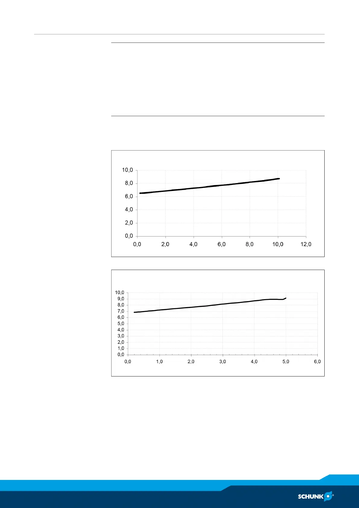
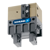
The output "Analog position output" (terminal 15) issues the
current gripper position in the form of an analog value after each
reference run and at any point in time.
The following diagram shows in which way the output voltage and
the position of the gripper are connected.
Analog position outputOutput voltage in V
Position in mm
Connection between analog position output (terminal 15) and position of the gripper
Note that the position may drift due to step losses. To counter this
drift, we recommend performing another reference run before the
deviation is too large for the application.