Start-up
03.00 | MEG 64 EC | Assembly and Operating Manual | en | 389203
31
5.5 Live mode
In order to safely grip a workpiece with a reproducible force
(within the specifications), we recommend performing the
gripping process in one of the two "live movement" modes.
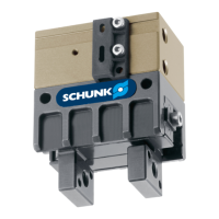
Live mode 1 is recommendable if you can rule out that the
workpiece to be gripped may be lost as a result of excessively
dynamic gripper movements (e.g. gripper on a 6-axis robot with
very dynamic swivel movements). In this mode the system-related
gripping force fluctuations are minimized (e.g. due to torque
fluctuations of the stepper motor). Once the gripper jaws arrive at
a resistance (workpiece), the gripper is only further provided with
current, but no longer actively clocked so as to allow for gentle
gripping.
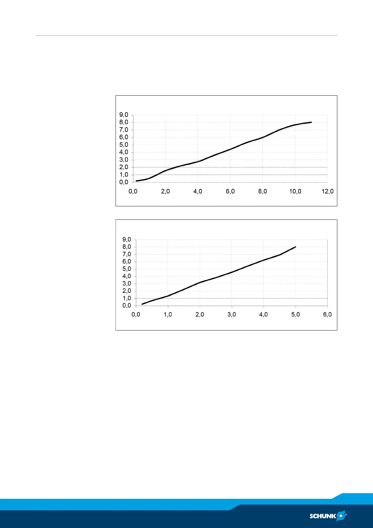
Live mode 2 is recommended if the above mentioned condition is
not fulfilled, i.e. to not loose the gripped workpiece when the
gripper is attached to a highly dynamic axis and an inelastic
workpiece is to be force-fit gripped. The gripper drive is actively
clocked on during gripping. This means that the claw jaws move
against the resistance generated by the workpiece. This prevents
workpiece loss. With this method, system-related gripping force
fluctuations of +/-15% of the maximum force may occur.