Mounting / connection / programming of the AFS3 138 PMI
01.00|1372106_AFS3 13
17
6 Unscrew monitoring rod with M5 screw on clamping pin.
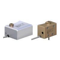
7 Mount inductive position measuring system PMI on bracket,
adjust to stop in direction of monitoring rod. Insert sensor
cable in cable bushing and fix onto cable outlet of the bracket.
Integrated sensors of the system into the control.
8 Perform functional test of the inductive proximity switch to
monitor the presence of the clamping pallet → open clamping
system → insert clamping pallet → close clamping system →
open clamping system → lift off clamping pallet.
9 Check signal output of the inductive proximity switch for
monitoring the presence of the clamping pallet; signal output
required for clamped clamping pallet; sensor can be readjusted
on the bracket.
10 Program inductive position measuring system PMI with
separately available teaching device (accessory).
11 Place the protective cover on vertically, integrated sealing bush
in cover plug, fix protective cover with fastening screws.
12 Monitoring system AFS3 138 PMI is operational.
Connecting the AFS3 138 PMI
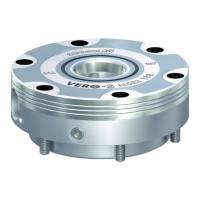
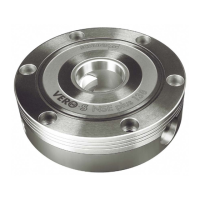
The PMI position measuring system monitors the end positions of
the clamping slide positions inductively.
When installing the AFS3 138 PMI to a NSE3, it comes adjusted and
operational directly from the factory.
When retrofitting, the AFS3 138 PMI must be adjusted to the
stroke positions of the clamping module using a programming
device. ( 6.3, Page 19)