SPECIFICATIONS
MECHANICAL PARTS REMOVAL/REPLACEMENT
15
SCIFIT Scientic Solutions For Fitness SCIFIT Scientic Solutions For Fitness SCIFIT
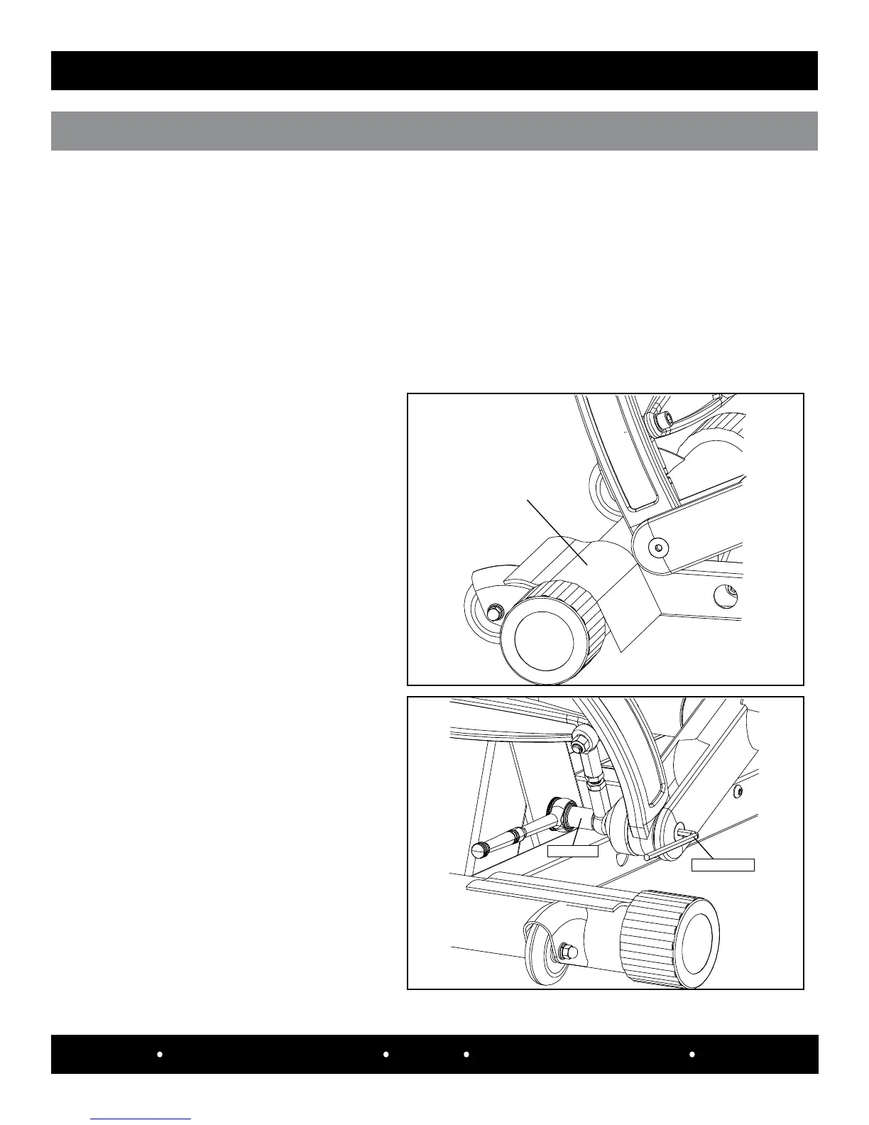
Place a 5/8” socket on the lock nut and
a 1/4” allen hex on the screw head that
secures the hardware, lower outer handle
and link assembly.
5/8” Socket
1/4” Allen Hex
Step 3:
Place a small cloth over the area where
the left transport wheel and endcap are
located. This will help protect the frame
from any damage.
Step 4a:
CLOTH
SPECIFICATIONS
LEFT oUTEr hAnDLE ASSEmBLy rEmovAL
Tools Required: * 7/32” Allen Hex * 1/ 4” Allen Hex * 5/ 8” Socket * R atchet
*Small at head screwdriver
Step 1:
Use the tools and follow the steps 1 thru 5 of the “Left Handlebar Removal” section (pages 5 thru 7).
Step 2:
Use the tools and follow steps 1 thru 3 of the “Left Angle Indicator Clamp Removal” section
(pages 12 and 13).