(A)
(B) x 4
(C)
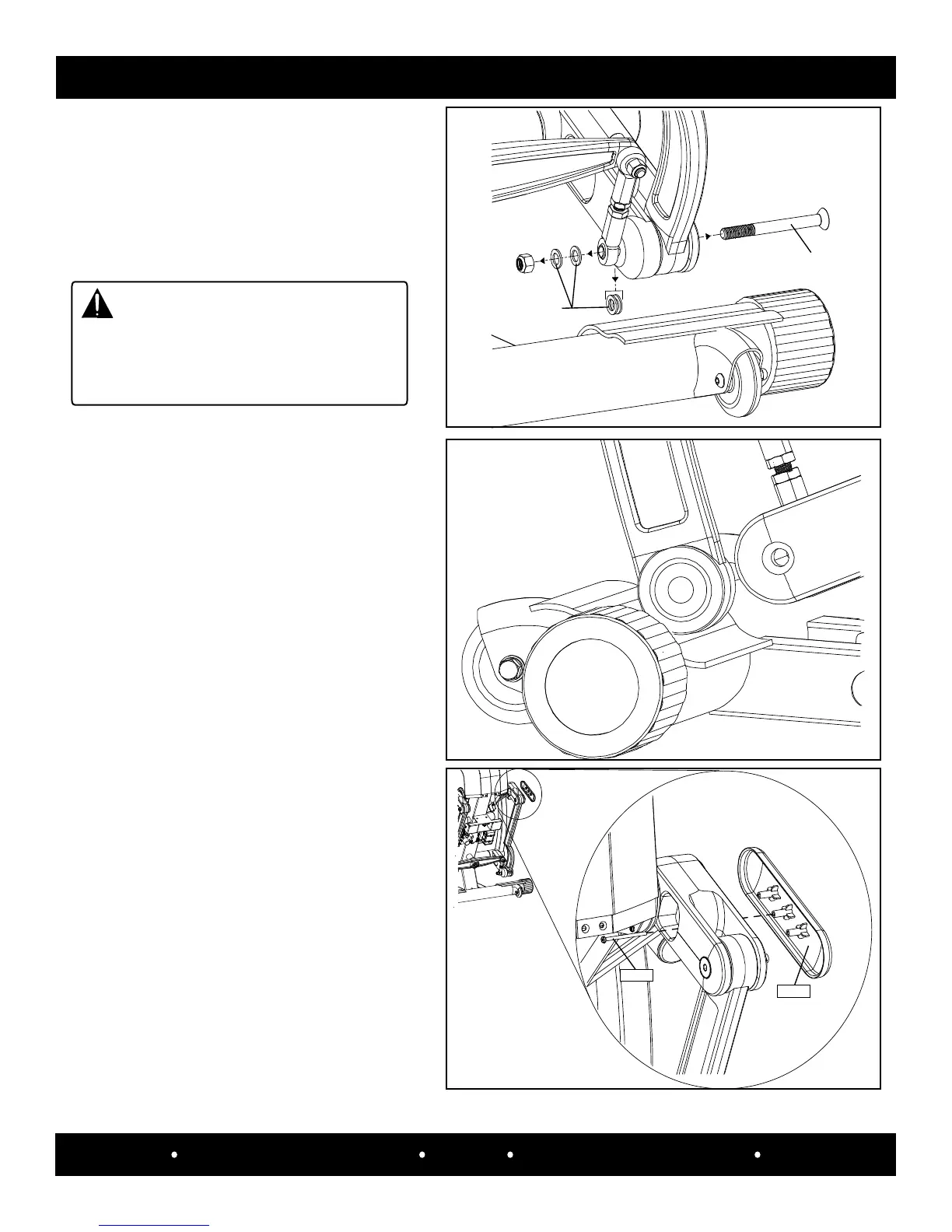
Step 3:
Remove the (a) 7/16-14 nylock
nut (#1137027), (b) four w ashers
(#10357-03641) a nd
(c) 7/16-14 x 4.5” black at head socket
screw (#10537-08048).
CAUTION
The outer handlebar will move freely
when the hardware is removed. Take
caution so the handlebar will not hit the
person(s) that are servicing the machine.
Step 4:
Place a towel on the front of the frame and
rest the unsecured assembly link blade on it,
so not to damage the blade.
SPECIFICATIONS
MECHANICAL PARTS REMOVAL/REPLACEMENT
33
SCIFIT Scientic Solutions For Fitness SCIFIT Scientic Solutions For Fitness SCIFIT
Use a right angle phillips screwdriver
to remove the #6 x 2” phillips screw
(#0142866) and the StepOne logo cover
(#A5027).
Screw
Cover
Step 5: