RCV-2 REDUCER/CYLINDER VALVE
In the following schedule, the item number refers to the components depicted in
Assembly Diagram and Parts List 5.3 provided at the end of this Module.
DESCRIPTION YEAR 1 YEAR 2 YEAR 3 YEAR 4 YEAR 5 OR 10
HOSE ASSEMBLY (ITEM 1) LEAK-TEST &
INSPECT
SEE SECTION
3.1
LEAK-TEST &
INSPECT
SEE SECTION
3.1
LEAK-TEST &
INSPECT
SEE SECTION
3.1
LEAK-TEST &
INSPECT
SEE SECTION
3.1
LEAK-TEST &
INSPECT
SEE SECTION
3.1
O-RING - SUPPLY HOSE (ITEM 2) LEAK-TEST LEAK-TEST LEAK-TEST LEAK-TEST RENEW
O-RING - HOOD CONNECTOR (ITEM 5) LEAK-TEST LEAK-TEST LEAK-TEST LEAK-TEST RENEW
4. SERVICING INSTRUCTIONS
WARNING:
Fully depressurise the system prior to servicing the reducer/cylinder valve.
CAUTION:
The charging adaptor must not be used to exert pressure when removing
components from, or attaching components to the reducer body.
Note:
Bracketed numbers in these instructions e.g: (4) refer to components depicted in the
Assembly Diagrams and Parts Lists at the end of this Module. Bracketed letters e.g:
(B) refer to the tools listed in Section 2 of this Module.
4.1
DISMANTLING THE REDUCER/CYLINDER VALVE
Note:
Bracketed numbers in this Section e.g: (4) refer to components depicted in Assembly
Diagrams and Parts Lists 5.1 and 5.2.
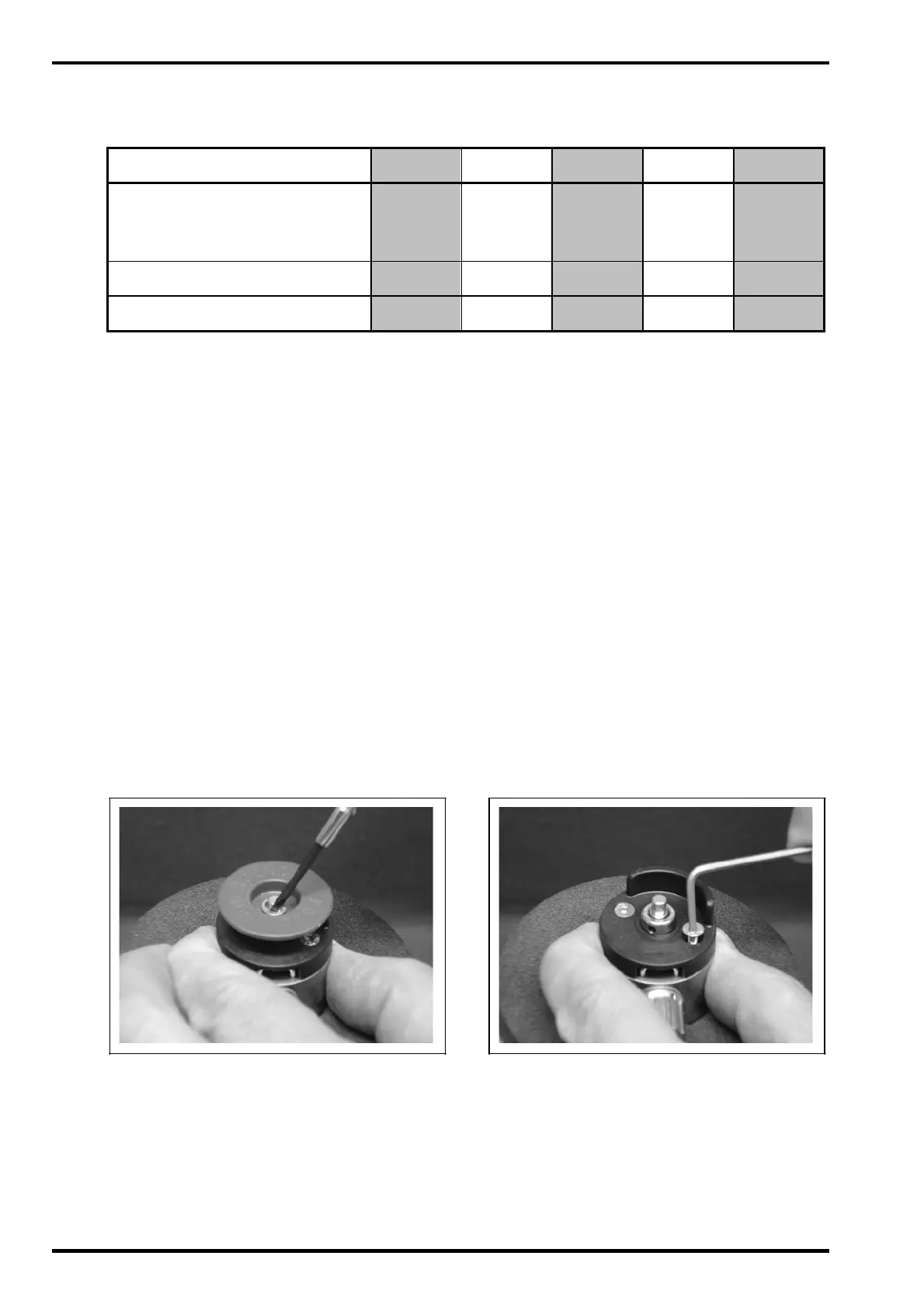
1.
Use Instrument Screwdriver (G) to remove circlip (2) and actuator disc (3).
2.
Use Allen Key (H) to unscrew reducer cap retaining screws (4). Remove
reducer cap (5).
RCV-2
(Page 4) Issue D 10. 2009
 Loading...