RCV-2 REDUCER/CYLINDER VALVE
4.8
REPLACING THE ACTUATOR O-RINGS
Note:
Bracketed numbers in this Section e.g: (4) refer to components depicted in Assembly
Diagrams and Parts Lists 5.1 and 5.2.
1.
Remove actuator assembly (14) from reducer head (18) as described in Section
4.1 of this Module.
2.
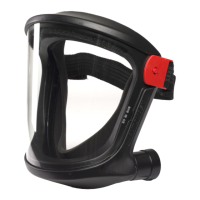
Use O-Ring Tool (I) to remove O-Rings (15 & 16). Discard O-Rings.
3.
Lightly lubricate replacement O-Rings (15 & 16) with Krytox Grease (K) and fit
onto actuator assembly (14).
4.
Insert actuator assembly (14) into reducer head (18) and secure in position with
U-Clip (9).
4.9
REPLACING THE BREATHING HOSE AND FITTINGS
Note:
Bracketed numbers in this Section e.g: (4) refer to components depicted in Assembly
Diagram and Parts List 5.3.
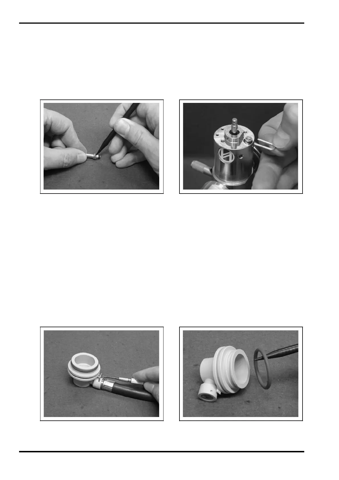
1.
Remove breathing hose assembly from reducer head as described in Section
4.1 of this Module.
RCV-2
(Page 12) Issue D 10. 2009

 Loading...