follows: IM_SEC3_02.01_en.docx
33/70
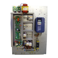
Connectors
On-board connectors are located in order to group all signals depending on their address (car, shaft,
machine room). Connectors name and pin numbering are printed on the board as follows:
• AUX Connection to board with auxiliary
relay SEC-3AUX
• SCB connection to SEC-3S safety circuit
board
• USB USB plug
• PRG software download
• RS232 remote connection
P1 (RECALL inputs)
1 NORM Normal (= Recall) NC
2 I_UP Inspection UP NC
3 I_DN Inspection DOWN NC
4 GND
P2 (load inputs)
1 OLD Overload NC
2 FLD Full load NO
3 MLD Minimum load NO
4 +24 VDC
5 GND
P3 (various I/O)
1 FID Fire racall NO
2 FRD Fireman’s drive NO
3 OSS Out of service NO
4 IN1 not used
5 OLI Overload output
6 OSI out of service output
7 ISP INSPECTION/RECALL output.
8 AF Alarm filter
9 +24 VDC
10 GND
P4 (encoder)
1 A encoder A
2 A encoder /A
3 B encoder B
4 B encoder /B
5 do not connect! +24VDC
6 encoder – GND
P5 (status inputs)
1 ZSP Zero speed NC
2 RDY Inverter READY NC
3 V3F OK Inverter FAULT NC
4 EME Emergency NO
5 END EME Emergency End
6 OCL Car light
7 SP Start Permit
8 +24 VDC
9 GND
P6 (drive outputs)
1 RLV Re-levelling
2 EME Emergency start
3 BRK Brake
4 MAIN Main contactor
5 common
6 common
P7 (supervision input)
1 MRM T Machine room temperat. NC
2 MOT T Motor temperature NC
3 GND
P8 (supply)
1 +24 VDC - Can2
2 +24 VDC - Emergency
3 +24 VDC - General
4 GND