Universal Radiographic System
Service Manual
SM-0524R4
24
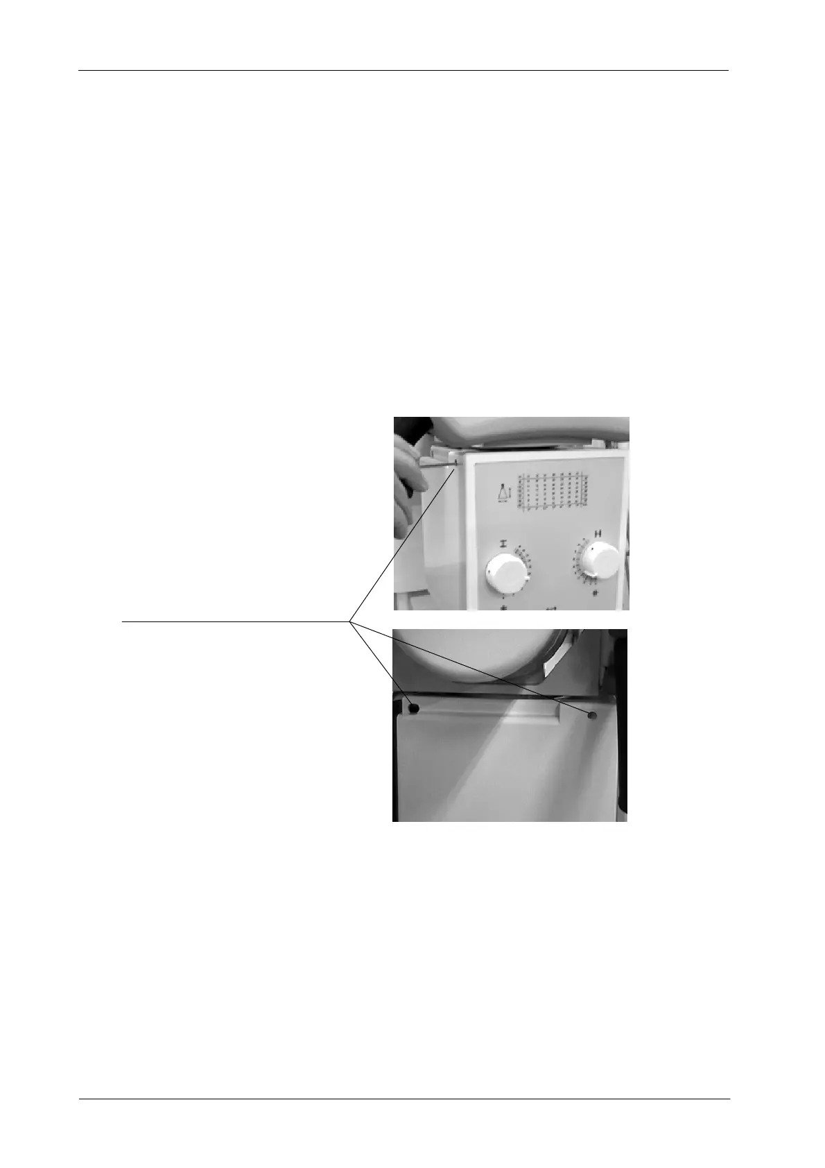
3. T urn on Collimator light and center the Collimator in relation to the Bucky
Table-Top. Horizontal and transversal position of the light axes projected
by the Collimator Lamp must be in line with the axes or film sizes marked
on the Table-Top.
If needed, modify Collimator position by carefully unscrewing and
screwing the four Centering Adjustment and Safety Screws (Allen) of
Collimator.
Illustration 4 -7
Collimator Screws
CENTERING ADJUSTMENT AND SAFETY SCREWS
4. Position the Collimator Test Tool (RMI model 161B) on the Bucky
Table-Top.
5. T urn on Collimator light and by means of the Collimator Control Knobs,
center the Collimator Test Tool with the light axes projected by the
Collimator Lamp.