Universal Radiographic System
Service Manual
SM-0524R4
25
6. Adjust the Light Field of the Collimator Lamp to the rectangle drawn
inside the Collimator Test Tool.
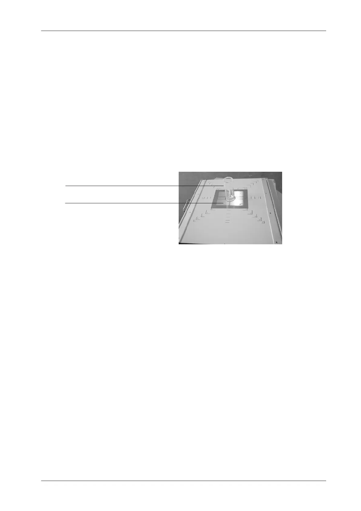
7. Place centered the Beam Alignment Test Tool (RMI model 162A) on the
Collimator Test Tool.
Illustration 4 -8
Alignment Test Tools
BEAM ALIGNMENT TEST TOOL -- RMA MODEL 162A
COLLIMATOR TEST TOOL -- RMA MODEL 161B
8. Load Cassette film Tray with cassette film 24x30 and insert it.
9. Make an exposure at 60 kVp / 5 mAs.
10. Process film and:
a. Check that the X-ray Field falls just within the image of the inner
rectangle of the Collimator Test Tool.
If an edge of the X-ray Field falls out of the inner rectangle means
a misalignment of the Light Field respect to the X-ray Field. The
maximum misalignment allowed is 2 % of SID (for SID 1m = 2 cm
tolerance).
Refer to Section 4.4.1 for alignment of Light Field with X-ray Field.