Universal Radiographic System
Service Manual
SM-0524R4
26
b. Check that the X-ray Beam is perpendicular to the plane of the
Image Receptor. If the Image receptor is parallel to the Table-Top,
the perpendicularity of the X-ray Beam can be checked using the
Beam Alignment Test Tool with the Collimator Test Tool.
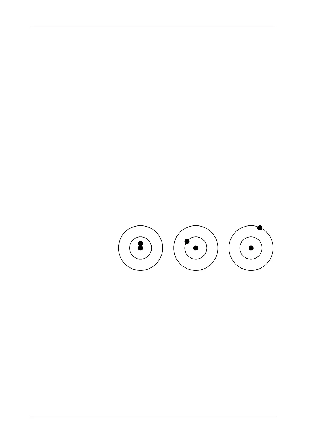
Based on next illustration, the criteria for SID at 1 meter is:
-- If the image of the two balls overlap (A) the X-ray Beam is
perpendicular to within 0.5
o
.
-- If the image of the top ball (larger shadow) intercepts the first
circle (B), the X-ray Beam is about 1.5
o
away from the
perpendicular.
-- If the image of the top ball (larger shadow) intercepts the second
circle (C), the X-ray Beam is about 3
o
away from the
perpendicular.
In cases (A) and (B) perpendicularity is within tolerance for SID at
1 meter (top ball is within or intercepting the first circle). The third
case (C) needs readjustment.
Refer to Section 4.4.2 for perpendicularity adjustment.
AB C
c. Check that the X-ray Beam is properly centered with the Image
Receptor. To determine the center of the Image Receptor, draw
diagonal lines from corner to corner of the X-ray Film. (Alternately,
the film can be folded in half and creased at the center). The two
lines will cross in the center of the Image Receptor (film). Then
draw diagonal lines from the corners of the imaged X-ray Field.
If the center of the X-ray Field and Image Receptor is the same,
the diagonals of both sets of lines should cross at the same point.
The maximum misalignment allowed is 2 % of SID (for SID 1m =
2 cm tolerance).
Refer to Section 4.4.3 for centering of X-ray Field and Image
Receptor.