508.366.1488 | www.semshred.com
38
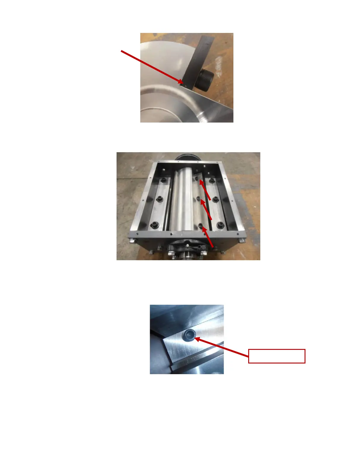
Figure 46. Beveled edge on rotor knife
Figure 47. Rotor knife bolts
2. Using a torque wrench and 5/16” Allen drive socket bit, torque rotor knife bolts to 50-55 ft-lb (Figure
47).
Figure 48. Rotor knife bolt
3. Set the clearance between the longest rotor knifes and two (front and rear) bed knives to 0.005” using a
feeler gauge (Figure 49) and the front and rear adjustment bolts (Figure 50 shows the two front
adjustment bolts. Two additional adjustment bolts are located on the rear). Turn the rotor in reverse
(clockwise) so the knives will not make flat-to-flat contact that cuts the feeler gauge.