508.366.1488 | www.semshred.com
39
NOTE: It is best practice to set the clearance for the longest knife only using this procedure. You will not
typically get all three knives to knock.
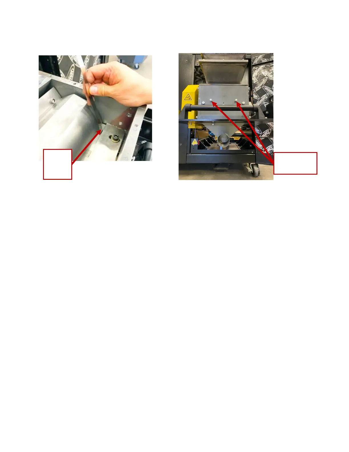
Figure 49. Measuring knife clearance with
a feeler gauge
Figure 50. Location of adjustment bolts
4. Using a 7/16” wrench and a 0.005” feeler gauge, perform this process in three locations on the two ends
of the longest rotor knife. Repeat the process until you get the correct clearance at both ends.
You will hear a light knock while spinning the rotor when one or two rotor knives come into contact with
the feeler gauge. This indicates proper clearance for all knives.
• There should be very little resistance, just a noise.
• If the rotor stops, there is too little clearance.
• The knocking typically occurs only on the longest of the three rotor knives. Occasionally it will
occur for two knives.
5. Check the clearance in front of each bed knife bolt. The knocking should occur either in the middle or on
the two outside bed knife bolts.
6. Torque the bed knife bolts to 45-50 ft-lb. Use the torque wrench and 5/16” Allen drive socket bit (Figure
51).
NOTE: Use the torque wrench only for the final tightening of all the bolts for all the knives. Use a socket
wrench for the initial tightening. Using the torque wrench for other than torquing the bolts could cause it to
become uncalibrated.
7. Double check the clearance after tightening the bolts. Check the gap at both ends of all three knives.