13
Chapter 1: Installation
ConneCTInG sensors
The Sentinel Pro is compatible with a wide variety of sensors including normally open/normally closed
contacts, 2.8K and 10K temperature sensors, and 4–20mA current sources. Compatible sensors and
accessories are shown on the Sentinel Pro website. Sensors may be connected while the device is pow-
ered on or off. A proper size screwdriver is provided for your convenience. Contact Sensaphone or your
Sensaphone reseller for assistance in selecting sensors for your monitoring requirements. A list of sen-
sors and accessories is shown in Appendix B. Follow the instructions below to properly wire and config-
ure the inputs for each type of electrical signal.
Warning: The inputs are designed to work with low voltage signals. DO NOT connect
voltages greater than 3.3V to the inputs. DO NOT connect 120VAC to the inputs.
GENERAL WIRING CONSIDERATIONS
Most dry contact sensors can be connected to the Sentinel Pro using inexpensive 2-conductor twisted-
pair cable as small as #24 AWG. For temperature and 4–20mA sensors, use the wire chart below as a ref-
erence for selecting the appropriate wire gauge. Note that if the sensor is located far from the unit or if
you are running cable in an electrically noisy environment, you should seriously consider using shielded
cable. This will shield the signal from electrical interference, thereby preventing false readings and/
or damage to the unit. For your convenience, Sensaphone has 22 gauge shielded cable available in 50’
lengths (part number FGD-0010). To minimize electrical noise coupling between sensor wires and other
wiring, follow the guidelines listed below:
• Route the power supply and network cables to the unit by a separate path then the wiring to the sen-
sor inputs. Where paths must cross, their intersection should be perpendicular.
• Do not run sensor wiring and AC power in the same conduit.
• Segregate wiring by signal type. Bundle wiring with similar electrical characteristics together.
• If shielded cable is used, tie the shield to the input ground terminal.
Wiring Minimum
Distance Wire Gauge
700’ #24 AWG
1500’ #22 AWG
2500’ #20 AWG
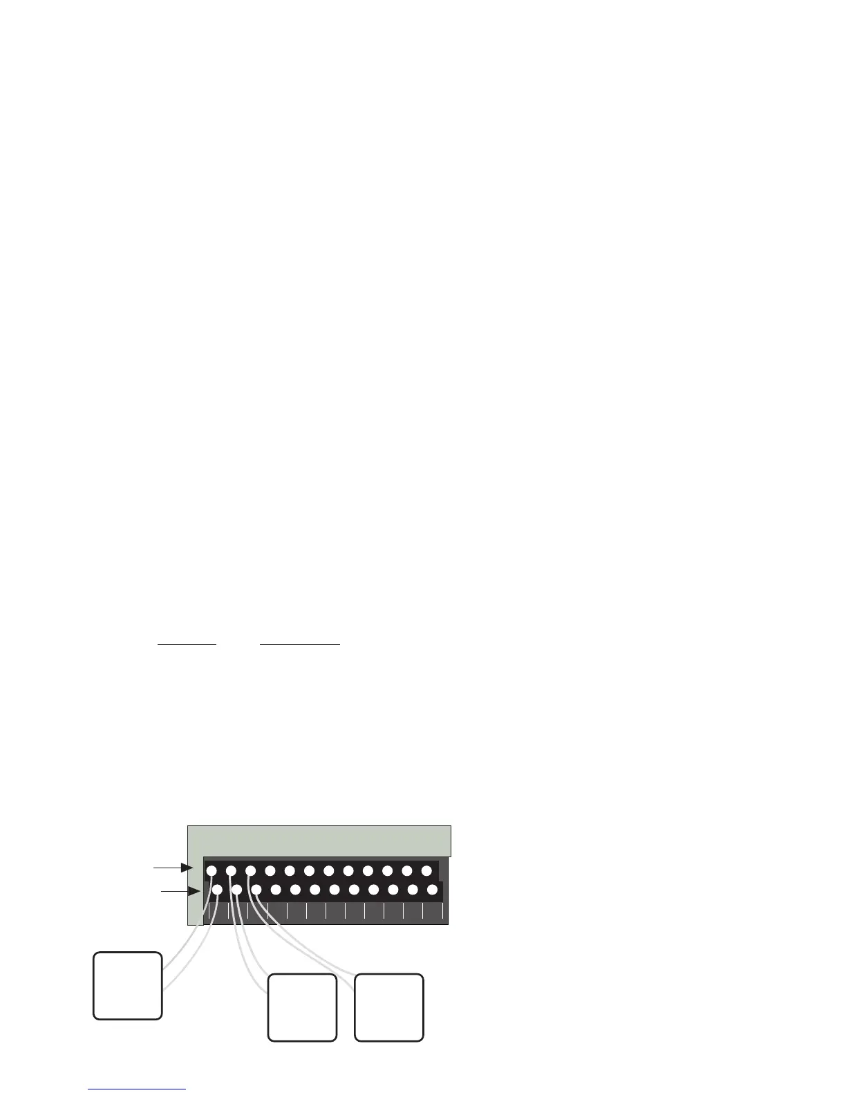
The zone terminal strip has an upper and lower level for connecting up to 12 sensors. The lower level
terminals are all “ground” and are electrically connected together. The upper terminal strip is the posi-
tive connection for each sensor. See illustration below.
2 3 4 5 6 7 8 9 10 11 121
Input Terminals +
Ground Terminals –
Sensor 1
Sensor 2
Sensor 3
 Loading...