15
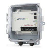
Chapter 1: Installation
department for assistance regarding your monitoring requirements (877-373-2700 or
support@sensaphone.com). Follow the wiring diagrams below for connecting a 4–20mA device:
External
24V
Power
Supply
FGD-0070
4-20 mA
Transducer
+
–
Wiring a 4–20mA device using an external 24 VDC supply.
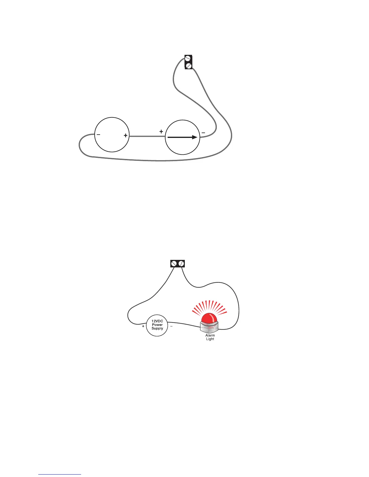
RELAY OUTPUT WIRING
The Sentinel Pro includes two relay outputs (switches) that can be used to turn on a light, siren, or other
device whenever an alarm occurs. The output are normally–open (i.e. off) dry contacts that can be used
for low voltage switching. The relays are rated for up to 30VAC/VDC 1 Amp. A sample wiring diagram
is shown below:
Relay
Output
The relays can be controlled manually (via the website or App) or automatically based on specific inputs
or alarms. See chapter 3 for details.
 Loading...