EasyManua.ls Logo

Sensitron MULTISCAN 8+ - Mainboard Layout and Features; Mainboard Layout and Connectors; Battery Disconnection Detection

Sensitron MULTISCAN 8+
Print Icon
To Next Page IconTo Next Page
To Previous Page IconTo Previous Page
Loading...
MT4221 Rev3
20/05/2020
41
Instruction Manual Multiscan 8+
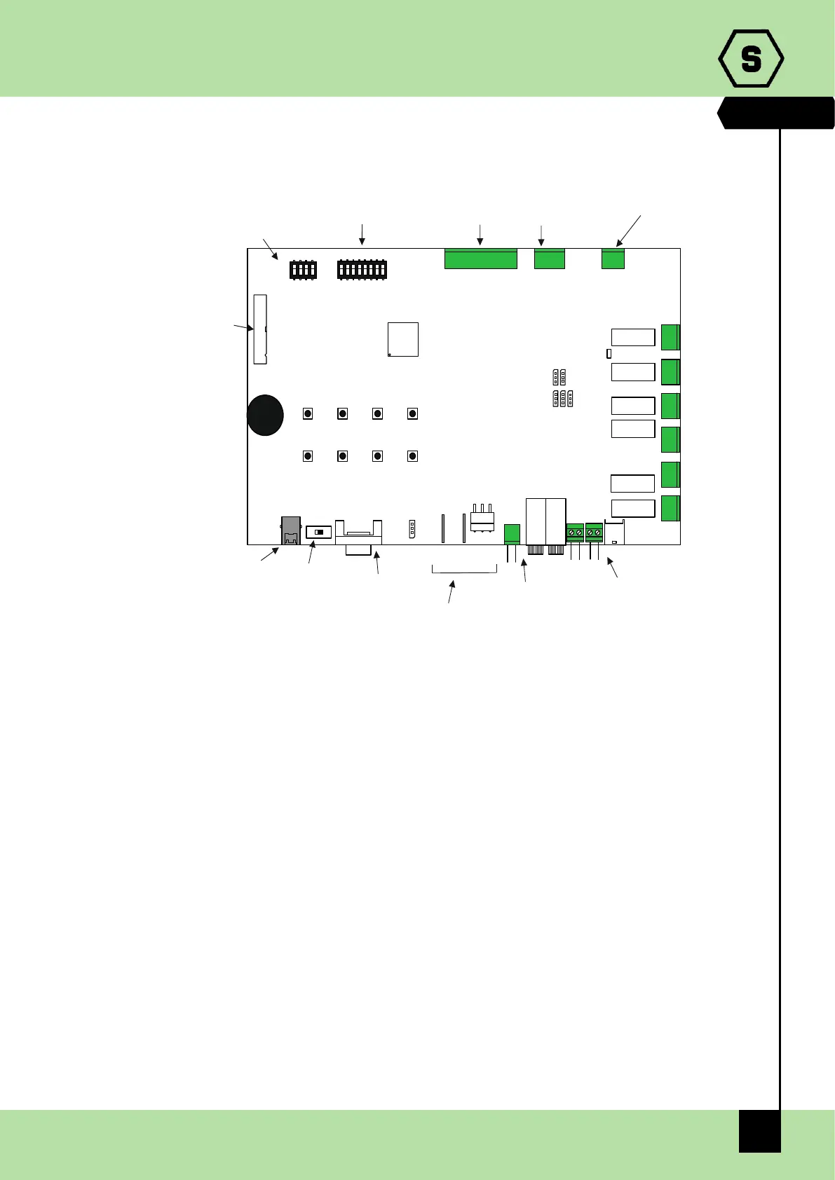
2.1.2 Central unit board layout
Fig. 2.1.2 Mainboard layout
2.1.3 Battery disconnection detector
MULTISCAN 8+ central unit allows the user to view if backup batteries have been
disconnected through a specific fault condition.
To enable this function backup batteries must be connected as shown in the figure 2.1 b),
then pins 2-3 of JP78 jumper must be closed. This jumper is located near JTAB2 faston
connector.
JP13
JP48JP70
F1 F2
JP47
JP51
JTAB1
JTAB2
JP
RS232 CONNECTOR
SW1
switch USB/RS232
USB CONNECTOR
BUZZER
RELAY BOARD STG/16REL
CONNECTOR
SD3
LANGUAGE SETTING
SD2
- BAUDRATE RS232 SETTING
- BAUDRATE RS485 SETTING
- RS485 PROTOCOL
- CONFIGURATION RESET
RELAY K1
RELAY K2
RELAY K3
RELAY K4
RELAY K5
RELAY K6
N.C.
C
N.A
C
N.A
N.C.
N.C.
C
N.A
N.C.
C
N.A
N.A
N.C.
C
C
N.A
N.C.
JP64
8 ANALOGUE INPUT
CONNECTOR
JP77
ANALOGUE INPUT
POWER SUPPLY
JP58
RS485 CONNECTOR
8 SELECTION BUTTONS
+ -
+ -
+ -
J 70 JP48p
AUXILIARY 24Vdc OUTPUTCPU POWER SUPPLY
BATTERY CONNECTION
: POWER SUPPLY J 51p
: CONTROL OF BASTERRY DISCONNECTIONJTAB1 E JTAB2

Table of Contents

Other manuals for Sensitron MULTISCAN 8+