Do you have a question about the Sensitron MULTISCAN 8+ and is the answer not in the manual?
Emphasizes reading the manual for safe installation, use, and servicing of the product.
Describes the manual's focus on product components, installation, and operation.
Introduces the MULTISCAN 8+ as a versatile central unit for gas detection systems.
Highlights SIL1 and ATEX certifications and unit features like relay management.
Illustrates the system's block diagram and connectivity options.
Provides ordering codes for the MULTISCAN 8+ control panel and its configuration.
Lists codes for optional remote modules and relay boards for system expansion.
Covers housing, inputs, outputs, serial ports, power, and display characteristics.
Defines the working and storage temperature and humidity ranges for the unit.
Guide to physically assembling the unit and making necessary electrical connections.
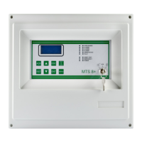
Identifies all major parts and connectors on the MULTISCAN 8+ central unit.
Details the arrangement of components and connectors on the central unit's mainboard.
Explains the function and setup for detecting battery disconnection.
Describes the layout, jumpers, and connections for the optional 16-relay board.
Configures communication speed (Baud Rate) and protocol using dip-switches.
Sets baud rates for RS232 and USB serial communication via dip-switches.
Explains the requirements for connecting devices via the RS485 serial bus.
Details connecting detectors with 4-20mA output signals to the unit.
Explains connecting detectors using the RS485 serial communication protocol.
Illustrates direct and STG/IN8-S module connections for 4-20mA detectors.
Shows system diagrams for connecting detectors via the RS485 bus.
Covers STG/IN8-S module connection, addressing, and Baud Rate setup.
Describes the STG/OUT16-S module's 16 Open Collector outputs and relay conversion.
Details the STG/8REL board for converting O/C outputs and its connection.
Explains using rotary switches for hexadecimal addressing of modules.
Provides a table for converting module addresses from hexadecimal to decimal.
Covers programming the unit via PC using dedicated software.
Details connecting the PC using RS232 serial port or USB.
Explains connecting the unit to a LAN/WAN network using the TCP/IP module.
Guides through the initial power-up sequence and 'Warm Up' phase.
Describes the key switch functions and general display navigation rules.
Defines the various system operating states: NORMAL, ALARM, FAULT, etc.
Details the normal display and the activation and information of alarm status.
Explains how to view specific alarm event details and severity.
Lists fault conditions and how to view fault event details.
Describes using test mode for maintenance without triggering alarms.
Explains UNSET/EMERGENCY modes and accessing menu functions.
Describes how to display and manage current active alarms and faults.
Details operations for acknowledging events and resetting them after resolution.
Outlines the warranty period and conditions for Sensitron products.
Specifies fields for recording installation details for warranty purposes.
Provides instructions for proper disposal of the device according to regulations.
States Sensitron's product development policy and publication disclaimers.
| Channels | 8 |
|---|---|
| Communication Interface | RS-485 |
| Power Supply | 24V DC |
| Input Type | Analog |
| Output Type | Digital |
| Operating Temperature | -20°C to 60°C |
| Weight | 500g |