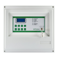
Detectors with 4-20 mA output directly connected to the central unit
Fig. 2.2.1 a) Direct connection of the 8 detectors to the central panel
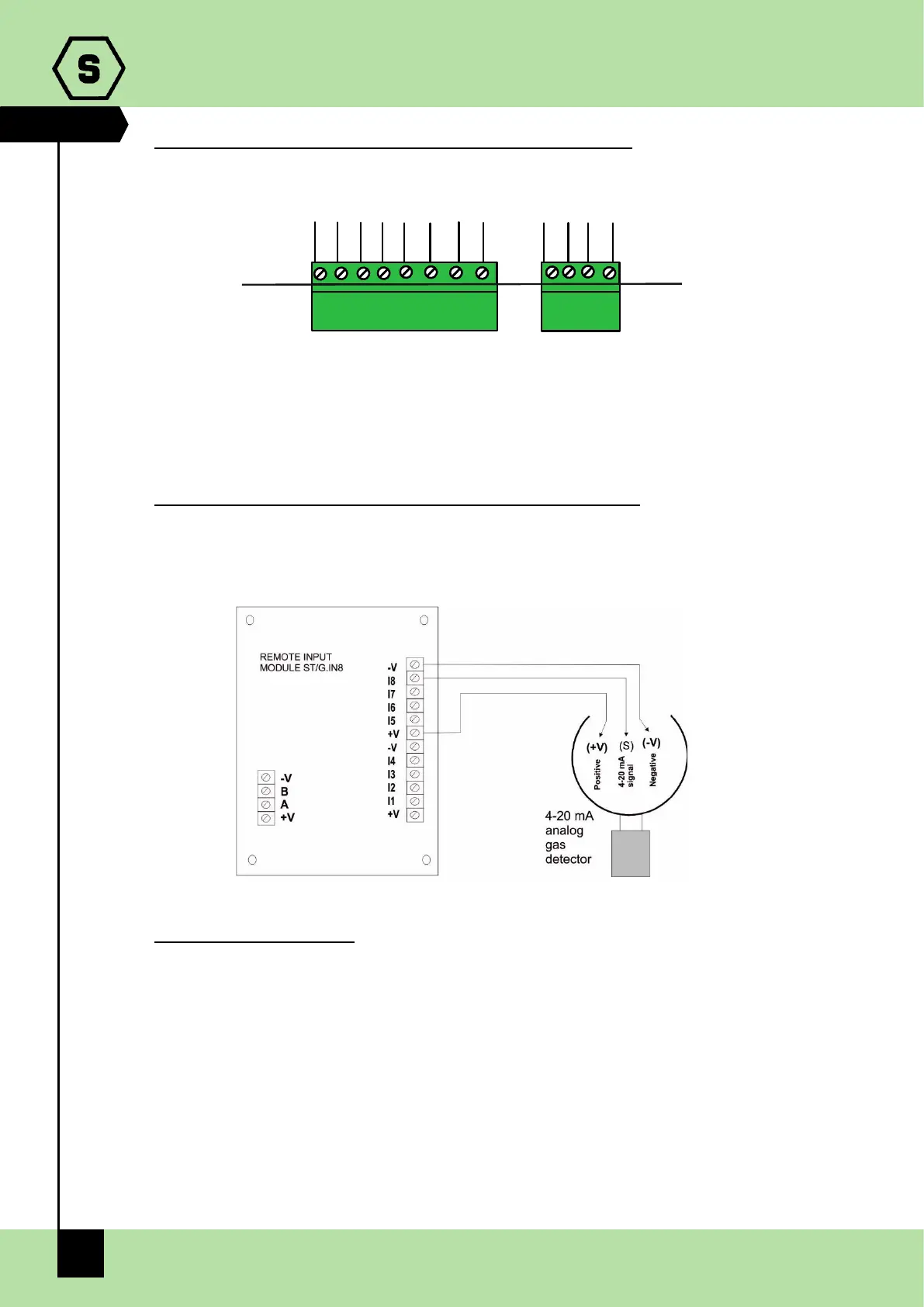
Detectors with a 4-20 mA output connected to the ST.G/IN8-S module
The following diagram shows the connection of a gas detector with a 4-20 mA output to
a STG/IN8-S input module. During system start-up, make sure that each gas detector
reaches a minimum voltage of 12 Vdc.
Fig. 2.2.1 b) Connection of the 8 detectors of the ST.G/IN8-S module
Detectors with RS485 output
Gas detectors provided with RS485 serial communication are connected directly to the
RS485 bus of the MULTISCAN 8+ central unit. The STG/IN8-S input module and
STG/OUT16-S output module are also connected to the RS485 bus.
4 conductors are needed for this type of connection: 2 for the RS485 serial and 2 for the
power supply of devices. For this reason, we suggest that two different wires or a single
wire is used. with the features described below.
-) The RS485 serial bus must be connected with an EIA RS 485 connection wire: No. 2 wires
with 0.22/0.35 mm2 section with shield (TWISTED PAIR). Nominal capacity between
conductors < 50 pF/m, nominal impedance 120 ohm. Total line length with this type of
connection must not exceed 1,000 metres. An example of a recommended cable is a
BELDEN 9841 or similar wire (EIA RS485 data transmission wire). Only connect detectors