Io
SENSOR
Section 2 SMT-200 Operations
SMT-200 Operations and Technical Manual 2.00/R1
21
The string on the previous page represents the string shown in the String menu. The above diagram shows
6 geophone elements wired as group A and group B. Both group A and B consist of 3 elements in series.
There are 2 parallel groups A and B. This information allows the SMT-200 to determine the strings
geometry. The string shown here incorporates damping resistors so the shunt option [2-1-7] should be set to
YES and the value [2-1-8] set to 1000. The geophone elements properties are known by the information set
in the Geophone menu [2-2]. The cable length can be calculated by multiplying the total number of elements
less one by the distance between elements and adding the lead-in cable distance. This can be converted to
a resistance by using the cable resistance that has been set in [2-1-4]. Once this information has been
temperature compensated [3-1] the SMT-200 has all the information it needs to know about the string.
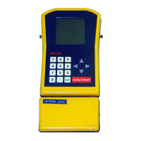
2.12.2.1.9 Limits menu
Sets maximum allowable limits for various tests
Low_Drive
Specifies drive level for the Low drive continuous
impedance test in percent. Input range is 1-99%
(default is 10% of nominal drive level).
Noise
Maximum limit allowable for ambient noise in mV.
Leak
Minimum allowable leakage in MΩ.
Max_Test
Maximum number of tests when Continuous mode
selected.
Bar_range
Specifies bar graph sensitivity for continuous
impedance test . Input range is 1-99% (default is
10%).
Pol_Sens
Specifies tap sensitivity for the Polarity test. Input
range is from 1-10 (default is 5).
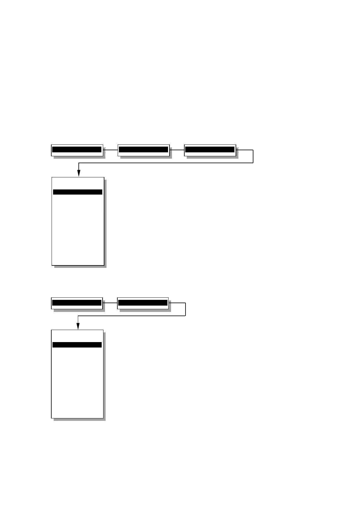
2.13.2.2 Geophone menu
Selects and modifies if required the type of geophone element used
Select
This is used to change the basic element type used
in the string.
Edit
Any of the basic geophone parameters can be
modified if required. It is not recommended to alter
the supplied specification for the Sensor strings.
Copy
Copy the selected element type to a new element
type. The original element description is
unchanged.
Delete
Removes the selected element description from
memory. Once deleted it cannot be recovered.
2>Setup menu...
1>String menu
5>Limits menu
Limits menu
----------------
1>Low
Drive 10%
2 Noise 10.0 mV
3 Leak 1000 Mohm
4 Max
Test 10
5 Bar-range 10%
6 Pol
Sens 5
0 Back to Setup
----------------
Low drive level
cont. impedance
2>Setup menu...
2>Geophone menu
Geophone menu
----------------
1>Select
2 Edit
3 Copy
4 Delete
0 Back to Setup
----------------
Select the spec:
Sensor-SM4