Io
SENSOR
Appendix A Connector Pinouts
SMT-200 Operations and Technical Manual 2.00/R1
89
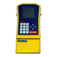
A.1 SMT-200 Bendix Connector
PIN NAME
A Charger V+
B Charger V-
C Geophone -
D Geophone +
E Geophone Leak
F Geophone Shield
G Smartec EXT
H Smartec V+
J Smartec GND
K ON/OFF
L DCD
M DSR
N RXD
P RTS
R TXD
S CTS
T DTR
U RI
V SG
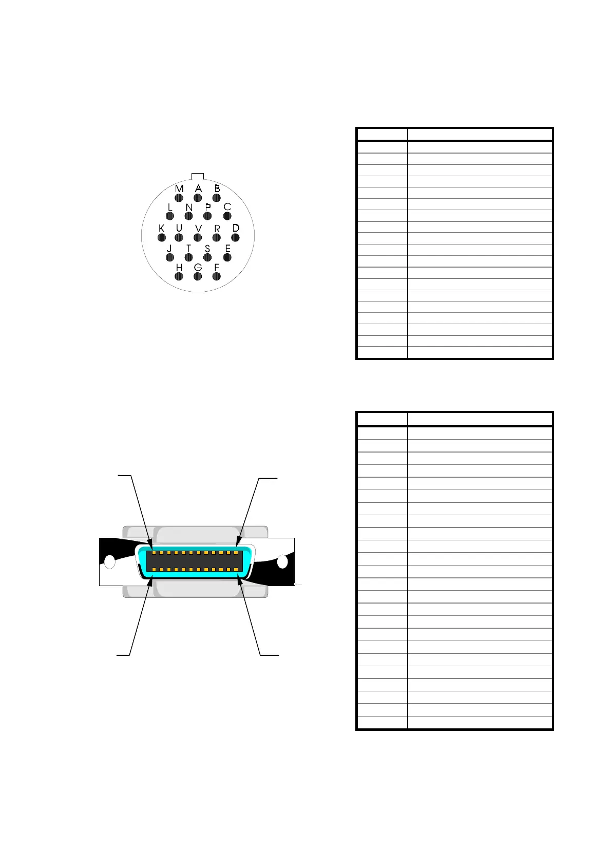
A.2 Docking Station SMT-200 Connector
PIN NAME
1 Charger V+
2 Charger V-
3 Shield
4 Geophone -
5 Geophone Leak
6 Smartec EXT
7 Smartec GND
8 Shield
9 DSR
10 (nc)
11 CTS
12 RI
13 Charger V+
14 Charger V-
15 (nc)
16 Geophone +
17 Geophone Shield
18 Smartec V+
19 ON/OFF
20 DCD
21 RXD
22 TXD
23 DTR
24 SG
(viewed into the male connector)
24 13
12 1
(view from rear of Docking Station)