Doc No. 006-0211-00 Rev AK Page 8 of 33
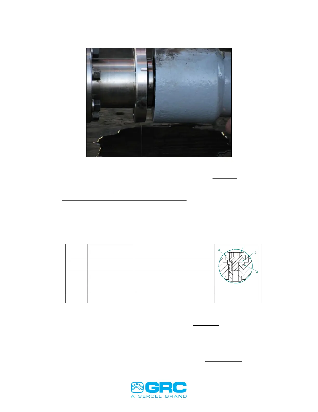
Figure 4: Gauge Stabbed into the Motor Base
4. Once the sensor has been stabbed as far as shown in FIGURE 4, finger-tighten
two of the motor base bolts at the top and bottom of the sensor to help support
the sensor weight. DO THIS BEFORE PROCEEDING TO STAB THE
SENSOR FULLY INTO THE MOTOR BASE.
5. Fully insert the sensor into the motor base making sure not to cut or pinch the
O-ring.
6. Install reaming bolts torque to minimum 25ft-lbs to insure proper seal.
7. To fill the sensor with oil, use either the drain and fill valve located at the
bottom of the sensor or through the drain and fill valve located on the motor.
GASKET, VENT & DRAIN
LEAD SEAL
Table 1: Drain and Fill Valve Part Numbers
Note: Both gaskets (Items 2 and 4) listed above are single-use components.
Item 3 (valve) should be torqued to 210 in-lbs, and Item 1 (plug) should be torqued to
100 in-lbs.
8. After the sensor is installed verify sensor readings using a Surface Readout
and record the values on the ESP Sensor Checklist APPENDIX 3.