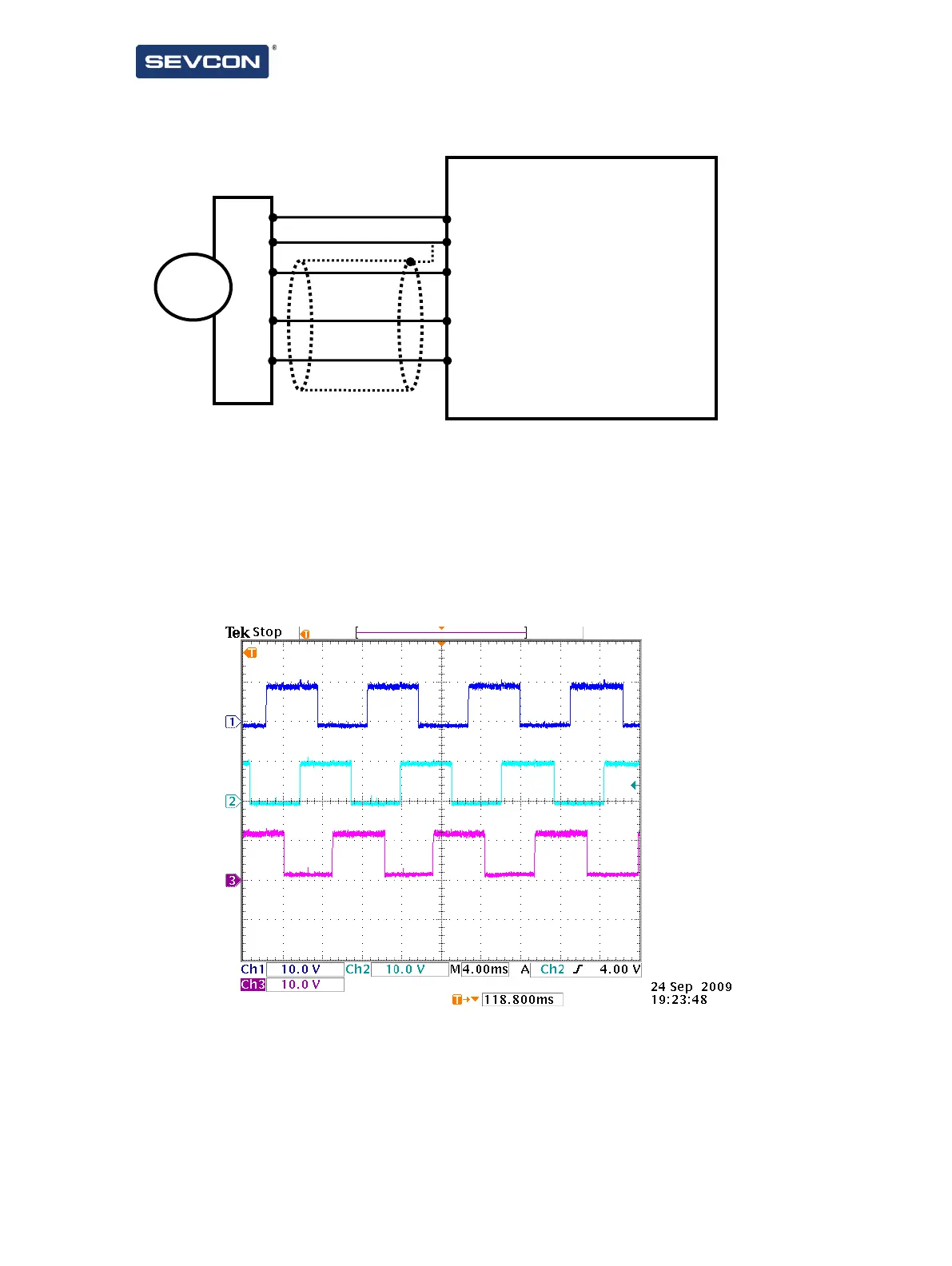
34
UVW Commutation Sensors
Figure 15 - Sample wiring for a UVW commutation sensor (encoder pin names may vary).
6 digital inputs are provided for differential UVW encoders, with a 5-10V power supply. The encoder
should provide one pulse on each UVW channel per electrical cycle of the motor, and each pulse should
be 120° out of phase with the others and have a 50% duty cycle. The RS422 inverse of these signals must
also be present on the ~U,~V,~W inputs.
Figure 16 shows an example pulse train for the U, V and W inputs.
Figure 16 - Example pulse train from a UVW commutation sensor