Configuration System/Accelerator
______________________________________________________________________________
MillipaK 4QPM Controller Manual Page 25 13/08/03
Accelerator Full /Zero Setting
The accelerator/analogue inputs are flexible in the range of signal sources they can accommodate
and can be adjusted to minimise dead-bands and mechanical tolerances. Each analogue input has
2 adjustments associated with it to allow the input voltage range to be determined.
For the Traction Accelerator, for example, the 2 adjustments are called the “Accelerator Zero
Level” and the “Accelerator Full Level”. If these were set to 0.20V and 4.80V then 0% pulsing
would start at 0.20V at the input, increasing to 100% pulsing at 4.80V. For accelerators with
decreasing voltage outputs, the Zero adjustment might be set to 3.5V and the Full adjustment to
0.0V. The Calibrator test menu shows the instantaneous voltage reading, and the equivalent %
“push” for each input.
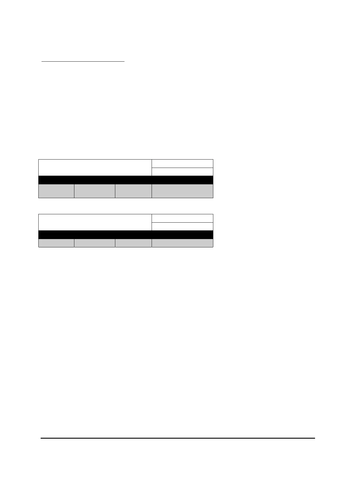
Immediate Accelerator Zero Volts
Calibrator Menu Reference:
2.05
Minimum Maximum Step Size Typical Value
0.00V 4.50V 0.02V
0.10V
Immediate Accelerator Full Volts
Calibrator Menu Reference:
2.06
Minimum Maximum Step Size Typical Value
0.00V 4.50V 0.02V 3.50V
Note that a 6 flash fault will occur if the full and zero levels are set within 0.50V of each other.
The PWM demand will vary between the Creep level and Maximum Speed level as the
accelerator voltage varies between “Accelerator Zero” and “Accelerator Full”.