Installation Wiring/Light
______________________________________________________________________________
MillipaK 4QPM Controller Manual Page 9 13/08/03
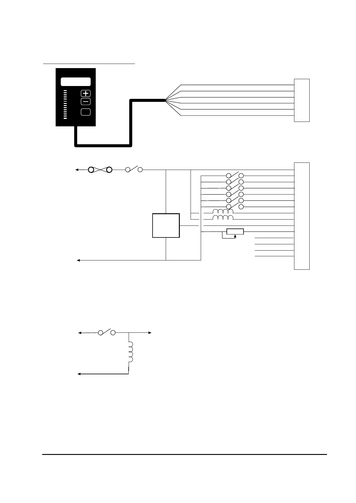
MillipaK Light Wiring example
1
2
3
4
5
6
0V
+ 10.5V
Clock
Dat a
Connector A
1
2
3
4
5
6
7
8
9
10
11
12
13
14
15
16
Connector B
Fus e
Bat t e r y +ve
Ke y-s w it ch
e.g.
Accel
Module
Forw ard (Dig 1)
Reverse (Dig 2)
FS1/ Be lly (Dig 3)
Seat / Tille r (Dig 4)
Digital Input 5
Bat t e r y -ve
Digital Input 6
Analogue Input 1
Analogue Input 2**
12V Output
CALIBRATOR
Sevcontrol
SEL
Analog
Calibrator Detect
Line Contactor*
Auxiliary Contactor*
Extra Suppression 1***
Extra Suppression 2***
Horn Suppression***
Bat t e r y +ve
Battery -ve
Extra Suppression 1 or 2
or Horn Suppression
External Contactor /
Hor n
NOTES:
*Contactor Coil Suppression fitted internally.
**Analogue Input 2 can also be configured as a digital input.
***Extra Suppression and Horn Suppression inputs to be used as show n below :
Figure 3: MillipaK Light Wiring