Calibrator Map
MillipaK 4QPM Controller Manual Page 63 13/08/03
F.W EAK
TIMER
SE A T
X2
X3
X4
X5
BAT T
MOTOR (V)
MOTOR (A)
TEMP
TEST
Motor
Set up
Power St eer
Timer
Seat Switch
Delay
Additional
Personalities
Sy st em
Set up
Fault Log
Speed
Estimate
Sy st em
Vo l t ages
Motor
Vo l t ages
Motor
Currents
Heatsink
T emperature
Test Menu
TOP
Navigation
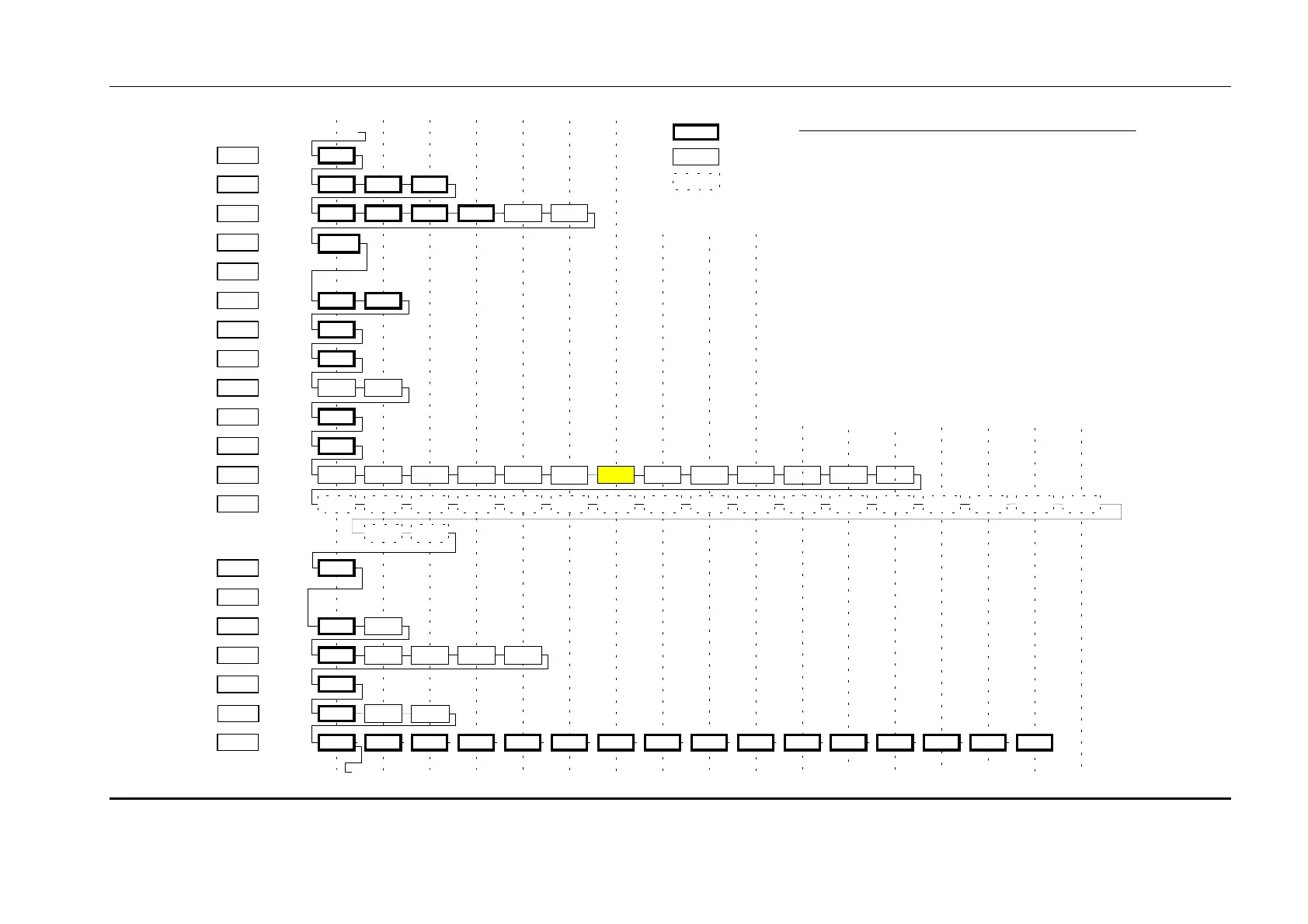
The operator moves through the Calibrator Map by pressing the SELECT key. The solid line shows the path the
through the menu structure when the SELECT key is pressed.
In Service Mode (no Password entered) only the items shown with a thick solid border are displayed. When the
next item is hidden (Engineering or All adjust access only), t he calibrator mov es on the next displayable item .
Items which are not configured will also be hidden, ie the bypass items will not be displayed if the bypass
contactor is not configured.
In Engineering Mode (Password entered) the items shown with a solid border are displayed. When the next item
is hidden (All adjust access only), the calibrator moves on the next displayable item. Items which are not
co nfigured will also be hidden .
In All Adjust Mode (Password entered) all the items (solid and dashed borders) are displayed.
Direction
By default , t h e Calibr at o r mo v es fr o m left t o right th ro ugh th e m en u st ruct ure. If t he op erat o r p r esses an d holds
the '+' and '-' keys for more than 1 second the navigation direction changes and the Calibrator will move from
right to left through the menu structure. T he direction can be restored by holding the '+' and '-' keys for 1 second
again.
T he direction is indicated by t he LED on the Bar Graph. If the LED is lit steadily, the direction is from left to
right, else if t he LED is flashing the direction is from right to left.
Information Items
The Test menu only shows information items that cannot be modified. The operator can move up
an d down t h e m enu usin g the '+' and '-' k ey s. As befo r e, it em s with a dash ed border are o nly disp lay ed in All
Adjust Mode. If the Operator presses the SELECT key the Calibrator moves to the next menu.
Item Identification
T he operator can identify the current item by holding down the '+' and '-' keys. For example, holding down the
'+' and '-' keys on the High V Cutout personality will display 11.09 (Menu 11 (I.MAX is menu 0), Item 9). The
operator will use the User Manual to identify the personality from the ID.
Calibrator
Reference
I.MAX
PLUG
ACCEL.
CREEP
BYPASS
SP E E D
SP E E D 1
SP E E D 2
Description
Current
Limits
Braking
Levels
Accelerator
Creep
Speed
Bypass
Maximum
Speed
Cutback
Speed 1
Cutback
Speed 2
TOP xxx
Service Level Access
xxx
Engineering Level Access
xxx
All Adjust Level Access
0
1
2
3
4
5
6
7
8
9
10
11
12
13
14
15
16
17
18
19
12
(18)
3
(19)
4
(20)
5
(21)
67
89
High V
Cutout
High V Start
Low V
Cutout
Line Dropout
Motor Prot
Low V Start
Seq D ir SW
PSS TimerPSS
Ra mp Up
Arm I Limit
Dir
Change
Neutral
Accel
Delay
Drive Decel
Accel
Zero V
Accel Full V
Creep Speed
Max. Speed
Cut Spd 2
Cut Spd 1
P. Steer T ime r
Seat Delay
Belly DelayRoll-off Walk Speed
Chop Select SRO E n a bl e
Control Mode
Roll-Off
Brae
Seat Cuts
Pump
Cap. Voltage
Battery Voltage
Arm. Voltage
Arm. Current
T emperature
10
11
Map for 4Q Controller System Version UK0076 - 19th June, 2002
Accel Char.
12
System Status
FBrake FullFBrake
Zero
Fo o t brake
13 14
High Speed
Mode
Q4
FET
Vo lt ag e
Q2
FET
Vo lt ag e
Point
A2
Voltage
Point
A1
Voltage
Rev Sp d FS1 Recy c.
15 16
Rev Speed
I Cubed
Lower Limit
I Cubed
Upper Limit
System
Voltage
17
Analo gue
Inputs
Belly Style
FBrake
Priority
Power Steer
Trigger
AccelDem Accel
Vo lt ag e
S/
W Version
Digital 6 SwitchDigital 5 SwitchDigital 4 SwitchDigital 3 SwitchDigital 2 SwitchDigital 1 Switch
Ser
No. Date
Ser
No. ID1
Ser
No. ID2
Aux. Demand
Aux.
Voltage
Dir Decel
Neut. Decel
S/W Revision Pers
Checksum
Line Dropout
Timer
Buzzer Alarm
Digit al I /O
Max
T emperature
Clear Max
T emperature
SRO Delay