ECShell engineering software
Manual – ECC-DFC field bus controller
8.5.4. Network Services
The Network Services window is used both for checking for reachable networks
and also for setting the IP address of a selected module. For more information,
refer to the "Use of the network help program" section.
8.5.5. Special Services
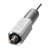
Each module operates a runtime meter for each motor roller that is connected to
the module. The value of the runtime is displayed as the Operating Time in the
main window. This window in the Advanced Dialog allows you to reset the
runtime meter when a motor roller has to be replaced.
Another function in the Special Services window is a button for remedying a mo-
tor roller short circuit. This particular fault cannot be remedied via the logic using
a timeout time or similar restart. A motor roller short circuit requires the module to
be switched off and on again or the “Reset” button to be pressed in this window.
This function is provided in ECShell in order to make the procedure easier and
prevent the module from having to be switched off and on again.
The final function in the Special Services window is “Touch and Go”. When this
function is activated, the motor roller detects movements on the roller surface and
transmits a wake-up signal in the relevant zone. If, for example, a box is placed in
the zone and gently pushed in the flow direction, the zone wakes up automatical-
ly. The function can be activated for both upstream and downstream zones using
check boxes in each case.
8.5.6. Use of sensor connection Aux I/O Pin 2
The function of pin 2 of the M8 connector at each of the two sensor connections
of a module is configurable. This pin can be used either as an input or an output.
The factory default setting for pin 2 is “Not Used”. One of the following functions
can be selected for each zone of the module via the “Pin 2 Usage” window from
the Advanced Dialog:
None: Ignore every input signal at pin 2
Accumulate: Input for local zone accumulation command
Wake up: Input for local zone wake-up signal
Lane Full Interface: Input for “Lane full” interface signal
Module error output
“Product in Zone” output
Sensor error output
Depending on how the module is configured, you can select which of these func-
tions should be present at which of the pin 2 signals of the two sensor connec-
tions.
 Loading...
