5
Electrical installation
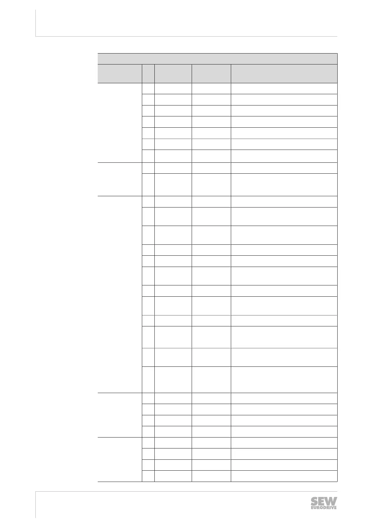
Terminal assignment
Operating Instructions – MOVIGEAR
®
performance
76
Assignment
Terminal No
.
Name Marking Function
X1
line terminals
1 L1 Brown Line connection, phase L1 – IN
2 L2 Black Line connection, phase L2 – IN
3 L3 Gray Line connection, phase L3 – IN
11 L1 Brown Line connection, phase L1 – OUT
12 L2 Black Line connection, phase L2 – OUT
13 L3 Gray Line connection, phase L3 – OUT
– PE – PE connection
X3
braking re-
sistor termin-
als
1 BR – Braking resistor connection
2 BR – Braking resistor connection
X9
control ter-
minals
1 F_STO_P1 Yellow Input STO+
2 F_STO_P1 Yellow Input STO+
(to loop through)
3 0V24_OUT – 0V24 reference potential
for DC24V auxiliary output
4 24V_OUT – DC24V auxiliary output
11 F_STO_M Yellow Input STO_ground
12 F_STO_M Yellow Input STO_ground
(to loop through)
13 24V_IN – DC24V supply
14 24V_IN – DC24V supply
(to loop through)
21 F_STO_P2 Yellow Input STO+
22 F_STO_P2 Yellow Input STO+
(to loop through)
23 0V24_IN – 0V24 reference potential
for DC 24 V supply
24 0V24_IN – 0V24 reference potential
for DC24V supply
(to loop through)
X42
fieldbus in-
terface
port1
1)
1 TX+ – Transmit line +
2 TX- – Transmit line -
3 RX+ – Receive line +
6 RX- – Receive line -
X43
fieldbus in-
terface
port2
1)
1 TX+ – Transmit line +
2 TX- – Transmit line -
3 RX+ – Receive line +
6 RX- – Receive line -
25945475/EN – 04/2019

 Loading...