AR-M256/M257/M258/M316/M317/M318/5625/5631 SIMULATION 8 - 8
When AR-F14N is installed
Note: Executable only when the finisher is installed.
Operation/procedure
After the paper size is set, the side guide plate and the rear guide plate
are set.
1. Enter the desired item with the 10-key, and press the [START] key.
2. Enter the adjustment value with the 10-key, and press the [START]
key.
There are 6 adjustment values for the side guide plate, and 12 for the
rear guide plate. The adjustment position is determined from the table
below according to the paper size.
Note: Executable only when the finisher is installed.
Operation/procedure
1. Touch the operation item to be set.
2. Enter the set value with the 10-key.
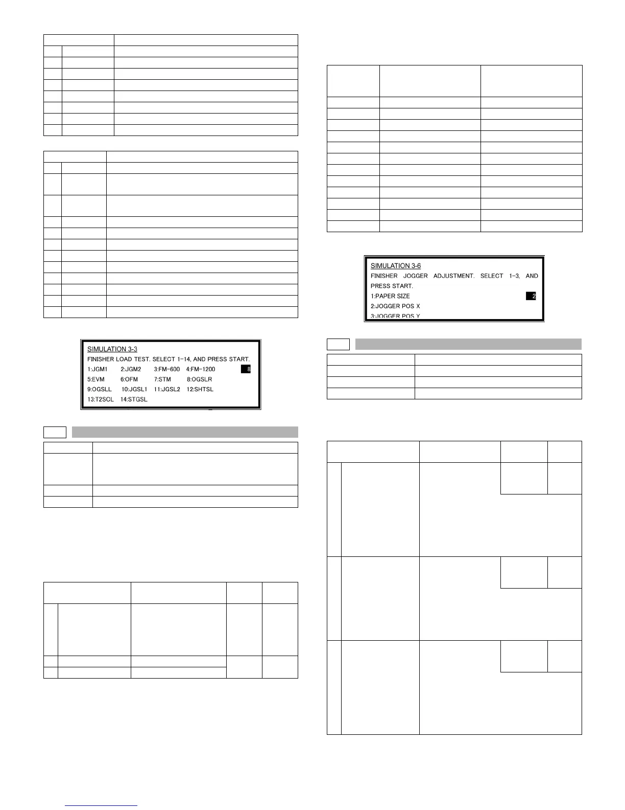
7 STM Staple operation motor
8 OGSLR Transport selection gate solenoid (R)
9 OGSLL Transport selection gate solenoid (L)
10 JGSL1 Rear edge plate drive solenoid
11 JGSL2 Upper alignment plate drive solenoid
12 SHTSL Shutter drive solenoid
13 T2SCL Paper exit roller clutch
14 STGSL Paper holding solenoid
Item Content
1 FFC Folding clutch
2FPSM
Punch side resist motor (Execution is possible only
when the punch unit is installed.)
3FPNM
Punch motor (Execution is possible only when the
punch unit is installed.)
4 FLM Shift motor
5 FFSM Stapler motor
6 FSM Slide motor
7 FRJM Alignment motor R
8 FFJM Alignment motor F
9 FAM Bundle exit motor
10 FPM Paddle motor
11 FFM Transport motor
12 FJM Interface transport motor
3-6
Purpose Adjustment
Function
(Purpose)
Used to adjust the alignment position (side regulation
plate, rear edge regulation plate) for each paper size.
Shifts to the specified paper size position.
Section Finisher
Item Operation
Item Content
Setting
range
Default
1 PAPER SIZE
Paper size
(1:A3, 2:A4, 3:B4, 4:B5,
5:A4R, 6:WLT, 7:LT,
8:LG, 9:FC, 10:LTR,
11:8K, 12:16K)
1-12 A4
2 JOGGER POS X Side guide plate
1-99 50
3 JOGGER POS Y Rear edge guide plate
Item Content
Paper size
Side guide plate
adjustment value number
Adjustment value number
of the rear edge guide
plate
A3 1 2
A4 1 9
B4 3 3
B5 3 10
A4R 5 6
WLT 2 1
LT 2 8
LG 4 4
FC 4 5
LT R 4 7
8K 6 11
16K 6 12
3-7
Purpose Adjustment
Function (Purpose) Used to adjust the offset tray operations.
Section Finisher
Item Operation
Item Content
Installation
range
Default
1
PAPER PUSH
TMG
Paper holder
descending timing
in non-staple
34-66 50
Used to adjust the descending timing of
the paper holder lever before lift-up
operation after paper exit or offset
operation. (The paper holder lever
prevents against paper shift in paper top
surface detection and paper stacking.)
2
PA PE R O U T
DOWN
Tray descending
distance after non-
staple paper exit
0-12 1
Used to adjust the offset tray descending
distance after non-staple paper exit.
The descending distance is the relative
distance from the non-staple standby
position.
3STAPLE UP
Tray lift distance
before staple paper
exit
0-12 6
The height of the tray standby position in
stapling is changed for that in non-stapling
to improve stacking capacity in stapling.
(The relative distance for the height of the
tray standby position in non-stapling is
set.)