LC-40/46/52LE820E, LC-40/46LU820E
4 – 14
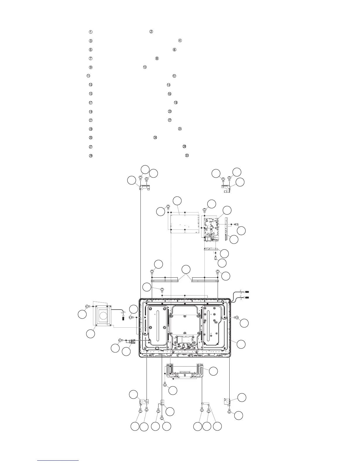
4. Removing of MAIN Unit, POWER Unit, Woofer, Stand Angle, 52” LCD Panel Module Unit.
1. Remove the 7 lock screws and detach the MAIN Unit .
2. Remove the 2 lock screws and detach the Terminal Angle (Bottom) .
3. Remove the 2 lock screws and detach the Terminal Angle (Side) .
4. Remove the 6 lock screws and detach the POWER Unit .
5. Remove the 4 lock screws and detach the Woofer .
6. Remove the 1 lock screw and detach the LCD Angle (Bottom-R) .
7. Remove the 2 lock screws and detach the LCD Angle (Top-L) .
8. Remove the 2 lock screws and detach the LCD Angle (Top-R) .
9. Remove the 2 lock screws and detach the LCD Angle (Bottom-L) .
10.Remove the 2 lock screws and detach the LCD Angle (B-C-A) .
11.Remove the 2 lock screws and detach the LCD Angle (B-C-B) .
12.Remove the 2 lock screws and detach the ECO Switch with Holder .
13.Remove the 6 lock screws and detach the Stand Angle .
14.Remove the 6 lock screws and detach the BL Chassis Support Angle .
15.Remove the 6 lock screws and detach the 52” LCD Panel Module Unit .
9
10
Woofer
[SB]
5
3
4
TERMINAL Angle
(Bottom)
6
TERMINAL Angle
(Side)
2 MAIN Unit
1
8 POWER
Unit
7
29
52" LCD Panel
Module Unit
29
30
[L1]
[L2]
29
25
26
Stand
Angle
12
11
LCD Angle
(Bottom-R)
22 LCD Angle
(B-C-B)
21
21
19
20
LCD Angle
(B-C-A)
19
18
17
17
LCD Angle
(Bottom-L)
23
24
ECO Switch
with Holder
16 LCD Angle
(Top-R)
15
15
14LCD Angle
(Top-L)
13
13
BL Chassis
Support Angle
27
27
28