MX-M753N MX-CF10 4 – 2
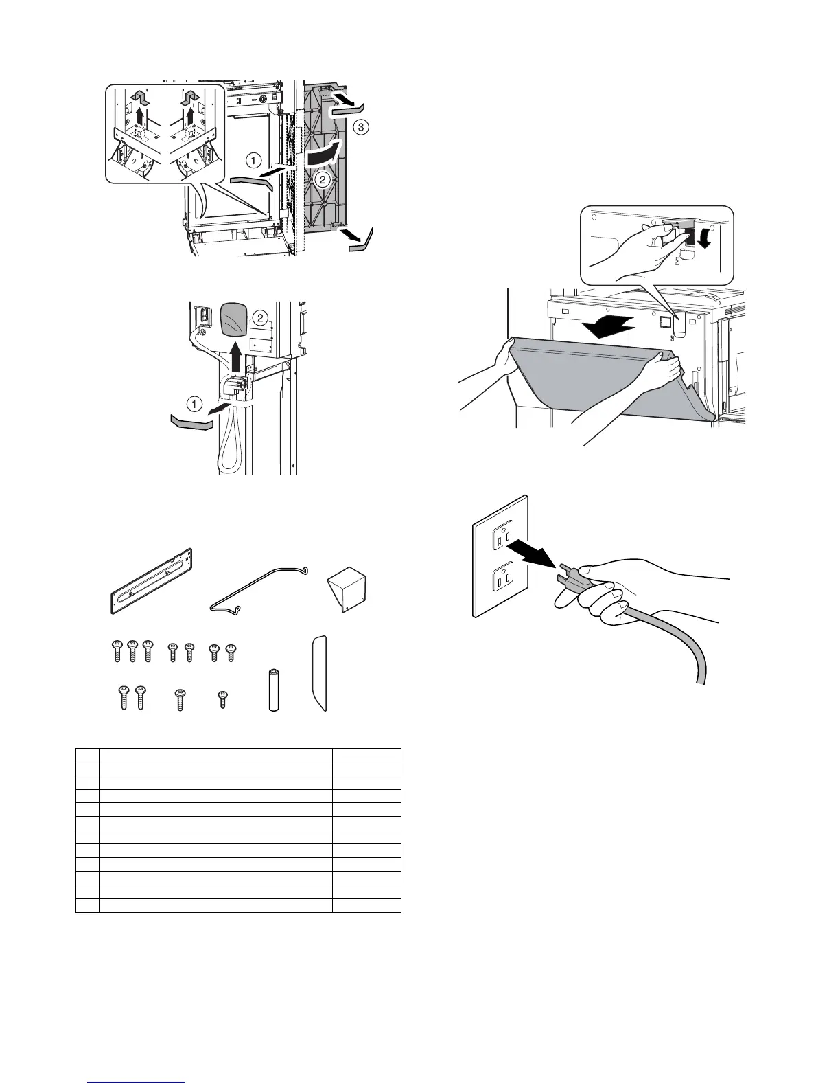
4) Remove the tape and open the base cover.
5) Remove the connector cable fixing tape.
C. Check the packed items
1) Check that all the items are included in the package.
* Uses only when the MX-FN14 is installed.
2. Installation
<Note before installation>
* Before starting installation, check to insure that the data lamp on
the operation panel is not on or blinking.
A. Turn off the power of the main unit
1) Turn OFF the power switch on the operation panel.
2) Open the front cabinet.
Turn OFF the power switch in the front cabinet of the main unit.
3) Disconnect the power plug of the main unit from the power out-
let.
Parts name Quantity
1 Positioning plate 1
2 Upper limit regulation wire 1
3 Button cover 1
4 Screw C (M4 x 12 small screw bind) 3
5 Screw D (M3 x 8 tapping bind) 2
6 Screw E (M4 x 7 small screw bind) 2
7 Screw F (M4 x 14 tapping bind) 2
8 Screw G (M4 x 12 tapping bind)* 1
9 Screw H (M4 x 6 small screw bind)* 1
10 Interlock pin* 1
11 Grip blinding sheet* 1
 Loading...