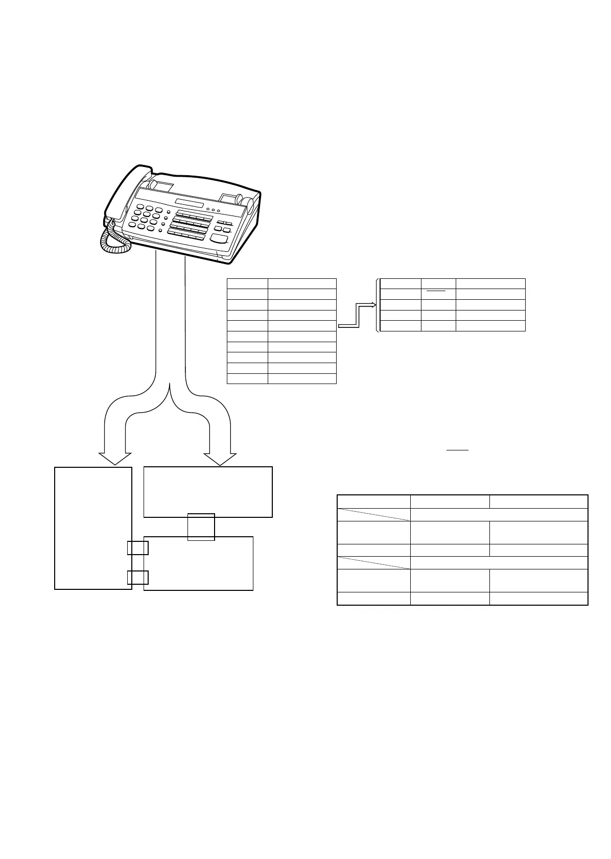
2. Description
2-1. Extension board unit
1. Remove the TEL/LIU PWB, control PWB and Power Supply PWB
from this unit, and mount the extension board unit instead.
• Before connecting the wiring to the extension board unit, set
the test PWB switches to the fixed position.
2. The setting is as follows.
The recording paper sensor (PSNS) and the hook switch are oper-
ated by OR of the mechanical unit switch and the test PWB switch.
When performing installation in the machine unit, set the test PWB
switches to the fixed position.
Mechanical unit PWB to be tested
Actual operation with mechanical unit
Recording paper
sensor
ON/OFF operation ON (Photo interrupter is
interrupted.)
Hook SW ON/OFF operation ON
PWB sensor check
Recording paper
sensor
ON ON/OFF operation
Hook SW ON ON/OFF operation
Connector Cable
CNTH2 QCNW-3872SCZZ
CNCCD2 QCNW-4569SCZZ
CNMT2 QCNW-4570SCZZ
CNSNS QCNW-4571SCZZ
CNPS 2 QCNW-4573SCZZ
CNLED2 QCNW-4574SCZZ
CNCSW2 QCNW-4575SCZZ
CNSP3 QCNW-4577SCZZ
CNPN2 QCNW-4583SCZZ
Cable color CNSNS Connected to (PWB)
1. Black PSNS CNLIUB-6
2. Brown RHS CNLIUA-7
3. Red HS1 N.C.
4. Orange HS2 N.C.
Cable
A set with a mounted
extension board unit
CNLIUA
CNLIUB
CHECK
CONTROL
PWB
CHECK
TEL/LIU
PWB
1
8
UX-177H
8 – 2