UX-B20U/UX-B20C/B25C
2 – 20
SW-D2 No. 4 Reserved
Set to "0".
SW-D2 No. 5 Caller ID function
Used for Caller ID function.
SW-D2 No. 6 Caller ID detect during CI off
Detection of caller ID signal is performed as follows:
0:First CI OFF only
1:All of CI OFF
SW-D2 No. 7, No. 8 Reserved
Set to "0".
SW-D3 No. 1 ~ No. 5 CI off detection timer (0-1550ms setting by
50ms step)
Set the minimum time period of CI signal interruption which affords to
be judged as a CI OFF section with 50ms steps.
(Example).
01110 (50ms ~ 14):
700ms (CI interruption>700ms:Judged as a CI OFF section)
The section 1 is not judged as a CI OFF section, the CI signal A is
counted as one signal.
The section 2 is judged as a CI OFF section, the CI signal B is
considered as the second signal.
00111 (50ms ~ 7):
350ms (CI interruption>350ms:Judged as a CI OFF section)
The section 1 is judged as a CI OFF section, and the CI signal A is
counted as two signals.
The section 2 is judged as a CI OFF section, and the CI signal B is
considered as the third signal.
SW-D3 No. 6 ~ No. 8 Reserved
Set to "0".
SW-E1 No. 1 ~ No. 8 Reserved
Set to "0".
SW-E2 No. 1 ~ No. 8 Reserved
Set to "0".
SW-E3 No. 1 ~ No. 8 Reserved
Set to "0".
SW-F1 No. 1, No. 2 DTMF detect time
Used to set detect time of DTMF (Dual Tone Multi Frequency) used in
remote reception (5 ).
The longer the detect time is, the less the error detection is caused by
noises.
SW-F1 No. 3 Protection of remote reception (5 ) detect
Used to set the function of remote reception (5 ). When set to
"1", the remote reception function is disabled.
SW-F1 No. 4 Remote reception with GE telephone
(Corresponding to TEL mode by GE) P. B. X.
"1": Compatible with TEL mode by GE
"0": Not compatible
• When sending (5 ) for remote reception with a GE manufac-
tured telephone remote reception may not take place because of
special specifications in their DTMF. To overcome this, a soft SW is
provided to change the modem setting to allow for remote recep-
tion.
• If this soft SW is set to "1", other telephone sets may be adversely
affected.
SW-F1 No. 5 ~ No. 8 Remote operation code figure by external
TEL (0 ~ 9)
Remote operation codes can be changed from 0 through 9. If set to
greater than 9, it defaults to 9. The "5 " is not changed.
Ex-7 (Default: 5 )
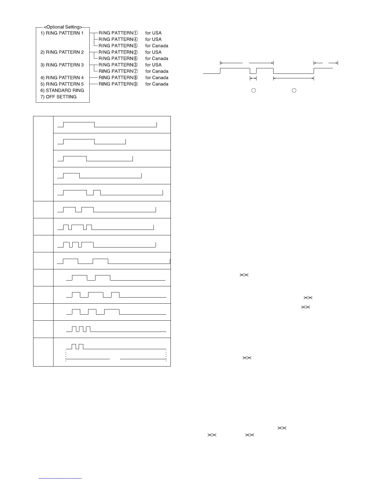
1S 1S
0.5S
RING
PATTERN 5
for CANADA
0.25S
0.25S
0.2S
6S
2S ring
4S ring
1.5S ring
3S ring
1S ring
4S ring
1.5S ring
4S ring
0.8S
4S ring
0.3S
4S ring
0.4S
4S ring
1S
4S ring
0.5S
0.5S
2S ring
2S ring
0.5S
0.5S
1S
0.2S
0.8S
0.4S
0.3S
0.2S
0.4S 0.8S
0.2S 0.2S
1S
1S
1S 0.5S
0.5S0.5S
0.5S
1S
0.5S0.5S
STANDARD
RING
PATTERN 1
for USA
RING
PATTERN 2
for USA
RING
PATTERN 3
for USA
RING
PATTERN 6
for CANADA
RING
PATTERN 7
for CANADA
RING
PATTERN 4
for USA
0.25S
0.25S
0.25S
0.2S
0.2S
RING
PATTERN 8
for CANADA
RING
PATTERN 9
for CANADA