UX-B20U/UX-B20C/B25C
5 – 17
[4] Circuit description of power supply PWB
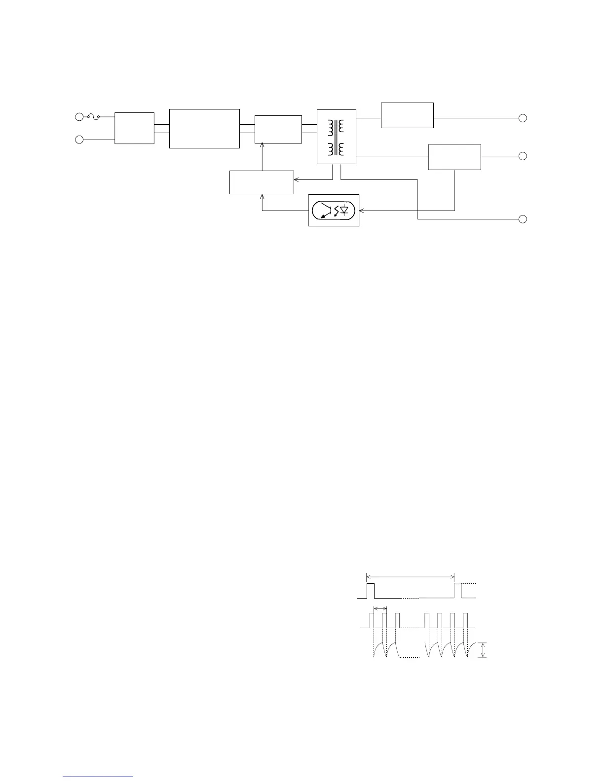
1. Block diagram
This power supply unit has the function to convert the AC 120 V (60 Hz) to DC 5 V, and provide these outputs to the equipment. The following
explains the function of each block.
2. Filter circuit block
This circuit reduces the outgoing noise through the input lines which is
generated in the power supply unit, and prevents the invasion of the
noise from the lines.(the excessive surge such as the thunder is pre-
vented by the varistor(Z1).)
3. Rectification and smoothing circuit block
This circuit rectifies and smoothes the AC input, and provides the DC
voltage to the switching circuit block.
4. Switching circuit block
This circuit converts the DC voltage (provided from the Rectification
and smoothing circuit block) to the high frequency pulse voltage by
FET(Q1)’s switching (on/off repeat), and provides the energy to the
transformer(T1). It discharges the energy (charged during the FET ON
time) to the secondary side during the FET OFF time through the sec-
ondary windings. The output voltage on the secondary side provided
by the energy depend on the ratio of the winding turns (primary : sec-
ondary) etc.
5. Control circuit block
This circuit block controls the output voltage by transmitting the
detected +5 V voltage to the primary control circuit through the photo-
coupler(PC1). In case of the over-current, this circuit reduces provid-
ing the energy to the transformer. In case of the over-voltage, this cir-
cuit reduces providing the energy to the transformer by letting the
Power-Zener(D104; connected between the +30 V output voltage and
GND) into the short mode and letting the over-current protection circuit
work.
6. +30V circuit block
This circuit block rectifies and smoothes the high-frequency pulse volt-
age provided by the transformer, and provides the DC +30 V output to
the equipment.
7. +5V circuit block
This circuit block rectifies and smoothes the high-frequency pulse volt-
age provided by the transformer, and provides about DC +5 V output
to the equipment. The output voltage is adjusted by the variable resis-
tor (VR101).
[5] Circuit description of CIS unit
1. CIS
Cis is an image sensor which puts the original paper in close contact
with the full-size sensor for scanning, being a monochromatic type with
the pixel number of 1,728 dots and the main scanning density of 8
dots/mm.
It is composed of sensor, rod lens, LED light source, light-conductive
plate, control circuit and so on, and the reading line and focus are pre-
viously adjusted as the unit.
Due to the full-size sensor, the focus distance is so short that the set is
changed from the light weight type to the compact type.
2. Waveforms
The following clock is supplied from SCE209L of the control board,
and VO is output.
Fig.8
(2) (3)
FILTER
CIRCUIT
BLOCK
RECTIFICATION
AND SMOOTHING
CIRCUIT BLOCK
(4)
(5)
SWITCHING
CIRCUIT
BLOCK
CONTROL
CIRCUIT BLOCK
(6)
+30V CIRCUIT
BLOCK
TRANSFORMER
INPUT
(7)
+5V CIRCUIT
BLOCK
+30V
+5V
GND
PHOTO-COUPLER
Fig.9
5ms
2µs
0V
0.6V~2.6V
(White original paper)
Approx.3.3V
ΦT
CISCLK
VO