UX-B20U/UX-B20C/B25C
5 – 8
2.5. Modem block (CX06835)
2.5.1 Integrated Analog Control Resisters for CX06835
The CX06835 IA can be used as a Primary Integrated Analog (PIA) codec or as a Secondary Integrated Analog (SIA) codec, depending on the signal
connection with the SCE Controller ASIC device. In the SCE100 product, both the PIA and the SIA are packaged external to the SCE Controller
device, whereas in the SCE209, the PIA is packaged with the SCE209 Controller and the SIA is external.
The CX06835 IA provides gain, filtering, internal analog switching, and an internally sourced microphone bias output. The IA is controlled by three
control registers and an address register located in internal RAM space which are accessed via the modem interface memory. These registers pro-
vide individual controls for the IA’s inputs, outputs, gain settings, and switching.
The registers are located in internal DSP RAM. Each bit of each 8-bit IA control register has exactly the same meaning for the PIA and the SIA. The
LSB of each 16-bit address contents is used to control the PIA. The MSB of each 16-bit address contents is used to control the SIA.
The following table the PIA/SIA control register RAM access code.
• For changes made to IACR1 to be effective, the host must write to IAADD with a value of 0002h.
• For changes made to IACR2 to be effective, the host must write to IAADD with a value of 0006h.
• For changes made to IACR3 to be effective, the host must write to IAADD with a value of 0007h.
Configuration default values are shown below.
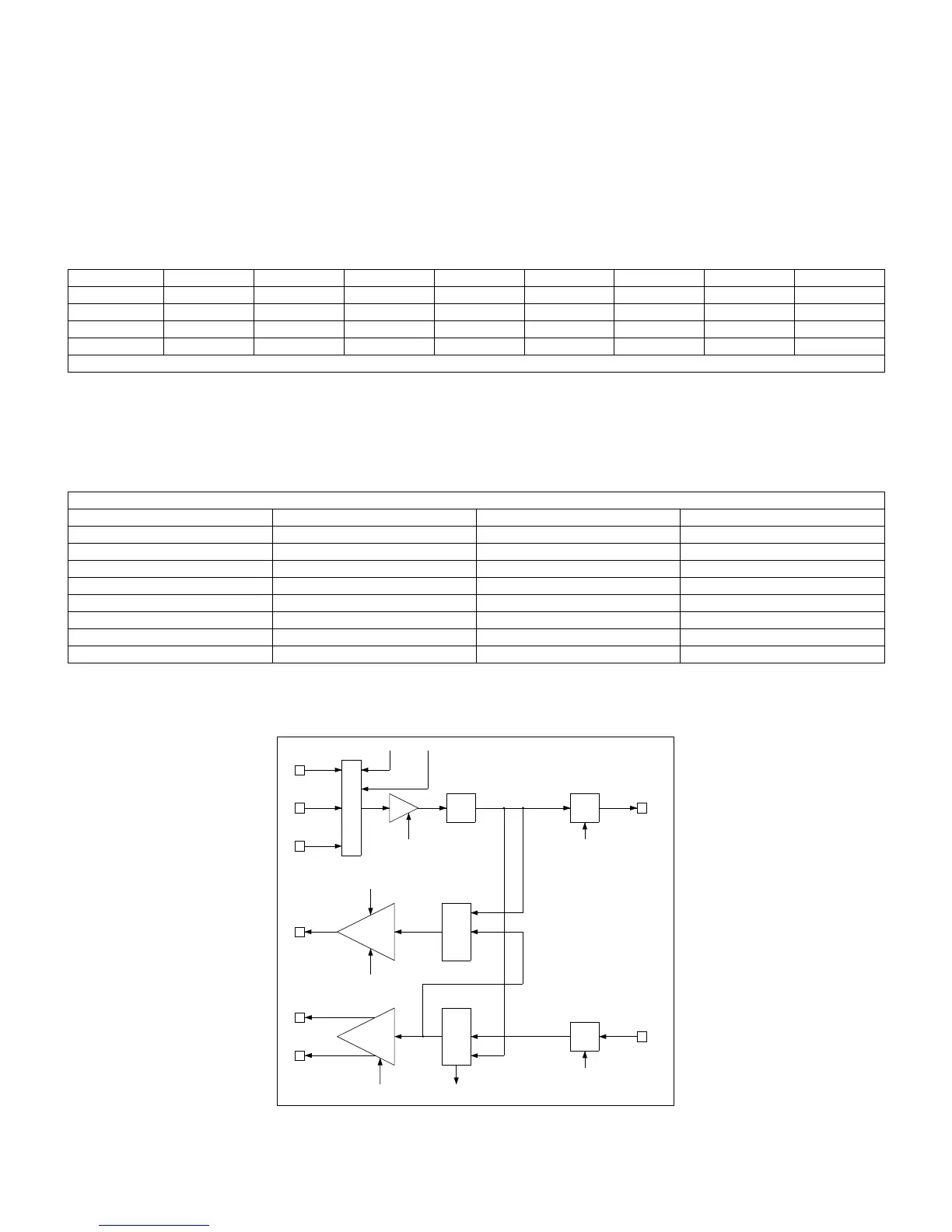
The following signal flow block diagram is for a signal IA and it applies to both PIA and SIA.
Register SBRAMx BRx Crx IOx AREXx ADDx PIA Reg* SIA Reg*
IACR1 00000D001
IACR2 00000D401
IACR3 00000D501
IAADD 00000CE0, 10, 1
NOTES: *Registers to use when x=1. When x=2, add 10h.
DEFAULT VALUE
CONFIGURATION IACR1 IACR2 IACR3
V.17/V.33 1D9Eh 0008h 0000h
V.29 1D9Eh 0008h 0000h
V.27ter 1D9Eh 0008h 0000h
V.21 Ch. 2 1D9Eh 0008h 0000h
V.23/Caller ID 1D9Eh 0008h 0000h
Tone Transmit/Detect 1D9Eh 0008h 0000h
Voice/Audio Codec 0D16h 0008h 0000h
Speakerphone 0D16h 0008h 0000h
Fig. 4 PIA/SIA Signal Flow Control
MICP
MICM
LINEIN
MIC/LINE SELECT
LINE IN ENABLE MIC ENABLE
GAIN
LINE OUT ENABLE
LPF ADC
SOUT
0, 20, 25, 30 dB(MIC IN)
0dB(LINE IN)
LINE OUT
LINE
DRIVER
Mute, 0, -6, -12 dB
LINE IN
SELECT
SPKRP
SPEAKER
DRIVER
SPEAKER OUT ENABLE
SPKRM
RT
Loop
(1,1)
(1,0)
(1,0)
(1,1)
(0,1)
DAC
SIN
0, +4 dB
0,6dB
(0,0)
(0,0)