UX-B20U/UX-B20C/B25C
8 – 2
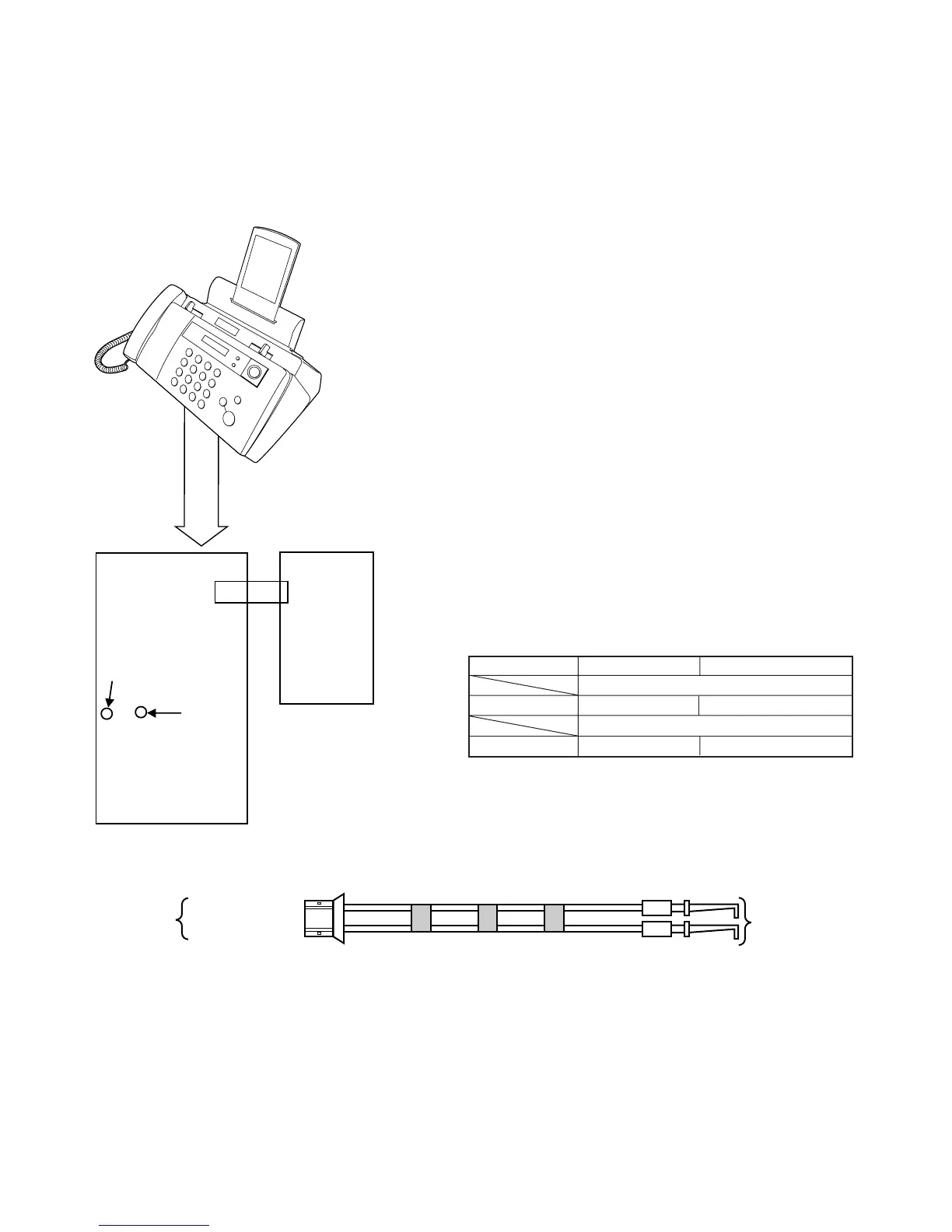
2. Relay board unit
2.1. Relay board unit
1. Remove the LIU, Control PWB and Power Supply PWB from this
unit, and mount the board unit instead.
Before connecting the wiring to the relay board unit, set the test
PWB switches to the fixed position.
2. The setting is as follows.
Extension
cable
CNLIU
CHECK
CONTROL
PWB
CHECK
LIU PWB
12
1
CNLIU
· The extension cables are used as one pair.
· The hook switch is manually operated.
PIN
(YELLOW)
+3.3V
(GREEN)
PIN EXTENSION CABLE (QCNWG231CSCZZ)
TO
CHECK
CONTROL PWB
TO
EXTENSION
PWB
PIN(YELLOW)
+3.3V(GREEN)
YELLOW
GREEN
The hook switch is operated by the mechanical unit switch and the test
PWB switch. When performing installation in the machine unit, set the
test PWB switches to the fixed position.
Mechanical unit PWB to be tested
Actual operation with mechanical unit
PWB sensor check
ON/OFF operation ON-HOOK
ON/OFF operationHook SW ON-HOOK
Hook SW