UX-P100U
UX-P200U
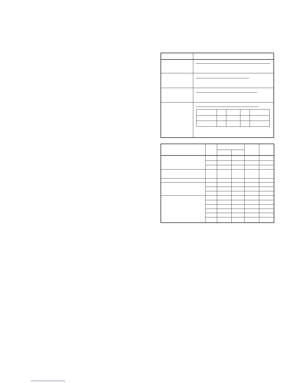
4) Signal selection
The following signals are used to control the transmission line of TEL/
FAX signal. For details, refer to the signal selector matrix table.
[Control signals from output port]
5 – 10
Signal Name Description
CML Line connecting relay and DP generating relay
(The circuit is located H: Line make
in the TEL/LIU PWB.) L: Line break
SP MUTE Speaker tone mute control signal
(The circuit is located H: Muting (Power down mode)
in the TEL/LIU PWB.) L: Muting cancel (Normal operation)
Handset reception mute control signal
TELMUTE H: Muting
L: Muting cancel
Handset receiver volume control signal
RCVOL
DTMFMUTE
(The circuit is located
in the control PWB.)
Note: The DTMF sending listed above is DTMF signal
sending in the handset OFF-HOOK mode.
Volume High Middle Low
DTMF sending
RCVOL
LHH H
DTMFMUTE L L H H
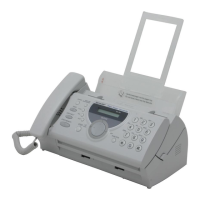
VOLUME SETTING
LINEOUT A RCVOL DTME
(HIGH) (LOW) MUTE
Receiver volume setting Low 1 1
High 0 0
Middle 1 0
DTMF Transmission Fixed 1 1
volume setting (Receiver)
Key buzzer volume setting Fixed
Speaker volume setting Low 1 1
Middle 1 0
High 0 1
Ringer volume setting Low 1 1
Middle 1 0
High 0 1
DTMF speaker volume Low 1 1
setting Middle 1 0
High 0 1
5. CI detection circuit
• CI is detected by the photo coupler which is integrated in series in
the primary side TEL circuit well proven in the existing unit.
6. Signal/DTMF transmission level & receiving level
•
Signal transmission level setting: ATT -8 dB Circuit output: -11 dBm.
• DTMF transmission level setting: HF -2.5 dBm LF -4.5 dBm
Thus, set the level.