22
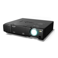
XV-Z12000
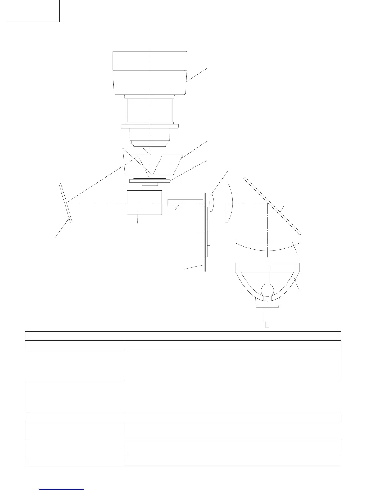
THE OPTICAL UNIT OUTLINE
Layout for proper setup of the optical components and parts (top view)
Lamp
Condensor lens
Condensor lens
IR-cut mirror
Light tunnel
Relay lens
Fold mirror
Color filter
DMD Chips
Projection lens
Prism
Item
1 Lamp
2 Condensor lens, IR-cut mirror
and light- tunnel
3 Color filter
4 Relay lens and fold mirror
5 Prism
6 DMD chip
7 Projection lens
Descriptions
The DC Light source lamp with parabola reflector.
The condensor lens leads the light generated from the lamp to the end sur-
face of the light-tunnel through the IR-cut mirror.
The IR-cut mirror is set in this unit to eliminate the excessive heat by the lamp
energy.
This color filter separates the white light into the 3 colors R,G and B.
A photo-sensor should be set in this unit to detect the transition timing prop-
erly between color filters.
The maximum rotating speed is 9000rpm.
This unit leads the illumination spot to effective area on DMD.
This prism also leads the illumination spot to effective area on DMD and at the
same time leads the reflection lights on the DMD to the projection lens.
This chip turns on and off in projection to each color component per dot de-
pending on the input source.
This lens enlarges and projects the incidend light coming from the DMD.
 Loading...