3-2. Mounting
CAUTION
In order to maintain safety and function, do not remove the case from the controller.
If the case of the controller has to be removed for replacement/repair, contact your nearest Shimaden agent.
Cut a hole for mounting the controller in the panel by referring to external dimentions and panel cutout in section 3-3.
The panel thickness should be 1.0 – 3.5 mm.
The controller is provided with tabs for mounting. Insert as is from the front surface of the panel.
Controllers of the SRS10A Series are designed for mounting on the panel. Be sure to mount on the panel.
Be sure to install this product with the attached gasket. Failure to do so could result in electric shock. After wiring, do not
touch terminal elements or other charged parts. Failure to do so could result in electric shock.
If mounted in series, provide ventilation so ambient temperature does not exceed 50°C due to temparature rise caused by heat
generation.
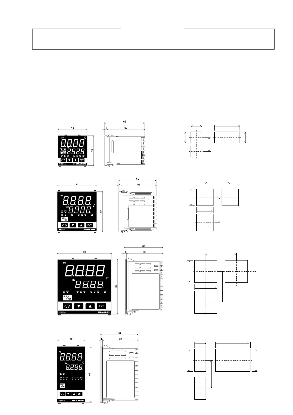
3-3. External dimensions and panel cutout
SRS11A
SRS12A
SRS13A
SRS14A
(48×N-3)
+1.0
-0
45
Min. 60
45
+0.6
-0
45
If mounted horizontally
N=Number of units
Panel cutout
+0.6
-0
+0.6
-0
Unit: mm
Min. 130
92
+0.8
-0
92
+0.8
-0
Min. 130
Panel cutout
Unit: mm
Min. 130
45
+0.6
-0
(48×N-3)
+1.0
-0
92
+0.8
-0
92
+0.8
-0
If mounted horizontally
N=Number of units
Panel cutout
Unit: mm
Min. 100
68
68
Min. 100
Panel cutout
Unit: mm
+0.7
-0
+0.7
-0
 Loading...