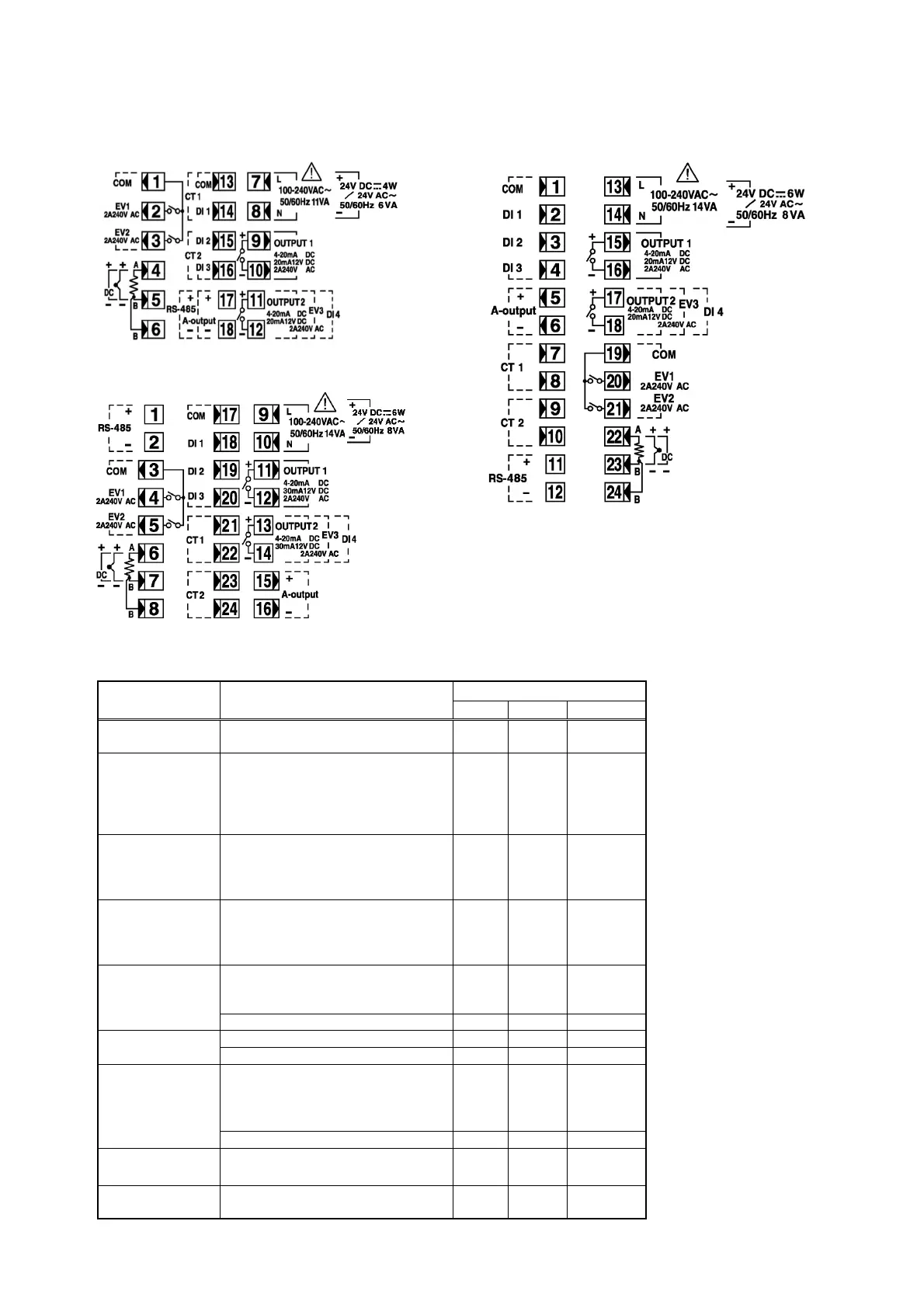
3-5. Terminal layout
Wire in accordance with the following terminal layout and terminal arrangement table.
SRS11A SRS13A/SRS14A
SRS12A
3-6. Terminal arrangement table
Name of
terminal
Description/code
Terminal No.
Note1:
With thermocouple / voltage /
current input, shorting across B
and B terminal will cause an
error.
Note2:
The following optional function
of the SRS10A Series are limited
to exclusive selection.
SRS11A:
Only one among control
output 2, event output 3 and
external control input DI4 can
be selected. Either CT input
or external control input DI1
– 3 can be selected.
Either analog output or
communication can be
selected.
SRS12A
Only one among control
SRS13A
output 2, event output 3 and
SRS14A
external control input DI4
can be selected.
SRS11A SRS12A SRS13A/14A
Power supply
100-240V AC/24V AC: L/24V DC: +
100-240V AC/24V AC: N/24V DC:
7
8
9
10
13
14
Input
R.T.D: A, thermocouple / voltage /
current: +
R.T.D: B, thermocouple / voltage /
current: –
R.T.D: B
4
5
6
6
7
8
22
23
24
Control output 1
Contact: NO, SSR drive voltage /
voltage / current: +
Contact: NO, SSR drive voltage /
volta
e / current:
9
10
11
12
15
16
Control output 2
(optional)
Contact: NO, SSR drive voltage /
voltage / current: +
Contact: NO, SSR drive voltage /
volta
e / current:
11
12
13
14
17
18
Event output
(optional)
COM
EV1
EV2
1
2
3
3
4
5
19
20
21
EV3 11-12 13-14 17-18
CT input
(optional)
CT1 input 13-14 21-22 7-8
CT2 input 15-16 23-24 9-10
External control
input / DI
(optional)
COM
DI1
DI2
DI3
13
14
15
16
17
18
19
20
1
2
3
4
DI4 11-12 13-14 17-18
Analog output
(optional)
+
–
17
18
15
16
5
6
Communication
(optional)
RS-485: +
RS-485:
17
18
1
2
11
12
 Loading...