VM-7 System Manual
Chapter 2 Description of the System
8
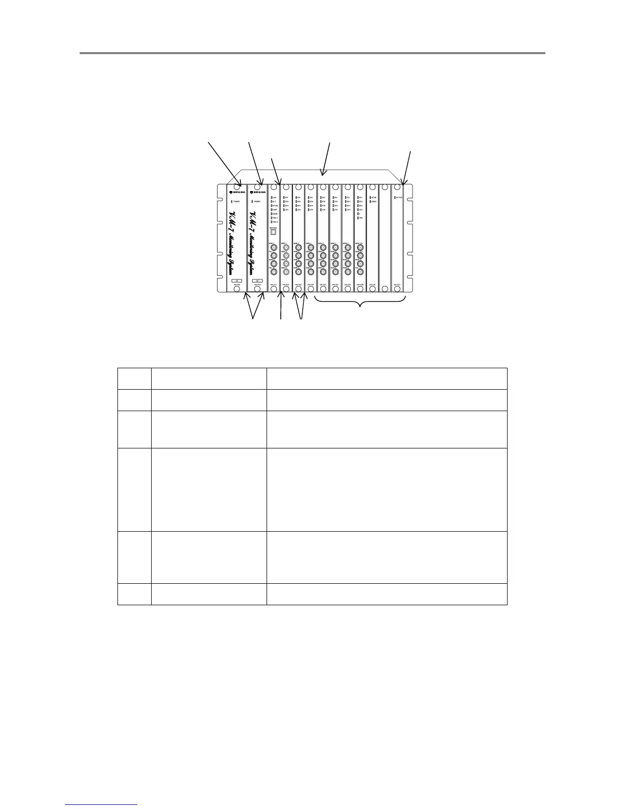
2.3 Unit part name and functions
VM-7 system monitor is provided with the slots, Slot 0 to 10, in which each module is installed.
No. Name Functions
①
Instrument Rack Accommodates modules.
②
Power Supply Module
Supplies power to modules.
Slot P1 is primary, and Slot P2 is secondary.
③
Local Communication &
Phase Marker Module
Displays measurement values and the status of each
unit through the MCL View, and perform settings
using FIELD CONFIG.
Also detects the phase marker signals.
This module can be installed on Slot 0 only.
④
Network
Communication Module
The measurement value and status of each module is
transmitted to the network.
This module can be installed on Slot 1 or 2.
⑤
Other Monitor Modules Monitors input signals.
c
d
e f
g
Slot 0
Slot 10
Slot P2 Slot P1
 Loading...