VM-741 LOCAL COMMUNICATION &
PHASE MARKER MODULE
Page 1 of 4
VM-7 SERIES
SPECIFICATIONS
30909E1.2
Issued Feb. 2009
Revised Mar. 2010
Non-incendive *
1
Custom set up Tropical spec. I/O terminal block for:
1
Class I Division 2 CSA
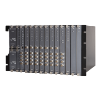
1 VM-761 instrument rack
2 VM-762 instrument rack
*1 In future
MCL VIEW (VM-771) COMMUNICATION
Network standard : 10Base-T
Connector : RJ45 (Rear side of rack)
FIELD CONFIG (VM-772) COMMUNICATION
Network standard : USB
Connector : USB Connector Type-B (Front side of rack)
ENVIRONMENTAL CONDITION
Operating temperature : 0 to +65°C
Storage temperature : -30 to +85°C
Relative humidity : 20 to 95%RH (noncondensing)
POWER CONSUMPTION
Module alone : Less than 15W
MATERIAL and FINISH
Face plate : ABS (Black)
Sheet : Polyester tough top (Gray)
Base plate : Alminium alloy (Silver)
MASS
Body : Max. 1.0kg ( 2.21lb )
ACCESSORY SPECIFICATION CODE / IDENTIFIED BY TB□
Code Accessory Quantity (Part Code)
/TB1 Transducer input terminal plug (15-pin)
FRONT-MC-1.5/15-STF-3.81(Phoenix Contact) :1piece (7072NAB)
Contact I/O terminal plug (6-pin)
FRONT-MC-1.5/6-STF-3.81(Phoenix Contact) :2pieces (7072NAC)
Note2)
/TB2 Contact I/O terminal plug (6-pin)
FRONT-MC-1.5/6-STF-3.81(Phoenix Contact) :2pieces (7072NAC)
Note2)
Note1) D-sub plugs and hoods are not included in this code. Please make
necessary arrangement seperately, if required.
Note2) When individually ordering specify the parts code,it is require to arrange
for a necessary amount.
OTHERS
PHASE MARKER INPUT
Max Input points (tachometer): Max. 2ch
Input Impedance : 50kΩ
Input voltage range : Less than 50Vp-p
Hysteresis : 1V, 2V, 5V
PHASE MARKER INPUT SENSOR
Proximity transducer : FK-202F
RD-05A
OPERATION CONTACT INPUT
RES : Outside reset signal
SEQ : Sequence signal
FIL : Filter enable signal
OUTPUT
Indicators : DAN LED (Red)
OR indication of DANGER alarm in the rack
For alarming : Lighting
ALT LED (Yellow)
OR indication of ALERT alarm in the rack
For alarming : Lighting
SYS-OK LED (Green)
OR indication of OK alarm in the rack including
POWER-OK
For alarming : Flashing, For normal : Lighting
D-BYP LED (Red)
For setting DANGER bypass : Lighting
COMM LED (Green)
For communicating with MCL view : Flashing
TRG LED (Yellow)
For normal : Lighting
For detected rotational pulse : Flashing
Monitor output : Input signal is output via a buffer amplifier
Location : Front side BNC and Rear side connector
Output Impedance : Approx. 100Ω
Output current : Max. 0.5mA
Pulse output : Shaped pulse signal is output via a buffer amplifier.
Location : Front side BNC and Rear side connector
Signal waveform : 0V(V
OL
), 5V(V
OH
)
Output Impedance : Approx. 1kΩ
Output current : Max. 5mA
Transducer power supply
proximity transducer
–24VDC / 25mA
Contact output : SYS-OK
Output points : 1
Contact type : Dry contact (SPDT)
Contact capacity : 250VAC / 5A, 30VDC / 5A
Specification
VM-741 /NB1 /CSU /TRP /TB
Model Code / Additional Spec. Code ( )
No entry if additional
spec, code is not specified.
 Loading...