VM-7 System Manual
Chapter 2 Description of the System
29
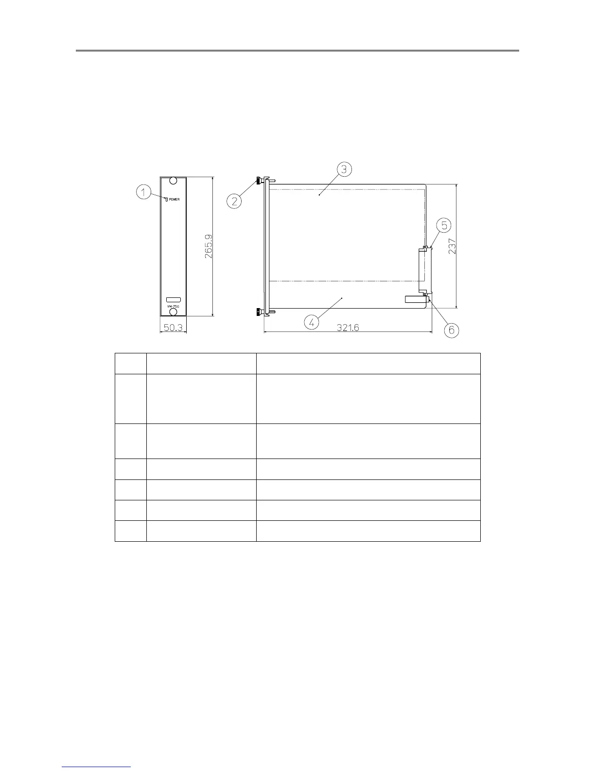
<Power Supply Module (VM-75)>
The Power Supply Module supplies DC powers to each module via a power bus.
Also, this informs of an output malfunction with the power status indicator and "Power-OK".
Mounting two Power Supply Modules enables a redundant power.
In this case, Slot P1 (left) becomes primary, and Slot P2 (right) becomes secondary.
No. Name Function
①
Power status indicator
When supplying power to each module: Lights (in
green)
When the power is not supplied: Does not light.
②
Module fastener
This is used to fix the Power supply module to the
instrument rack.
③
Heat sink fin A fin to radiate heat
④
Main board A board on which electronic parts are mounted
⑤
DIN connector A connector for connecting to the motherboard
⑥
Fuse holder A fuse is installed inside.
 Loading...