VM-7 System Manual
Chapter 2 Description of the System
22
<18-Channel Relay Module (VM-721)>
The 18-Channel Relay Module relates the DANGER, ALERT and OK alarm to a specific logic,
and outputs that result as a contact signal via the rear panel of the instrument rack.
The 18-Channel Relay Module can be installed on Slot 10 of the instrument rack only.
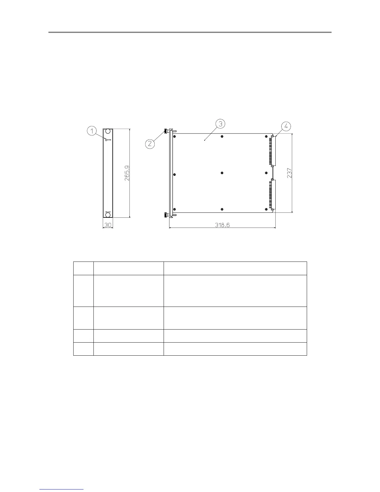
No. Name Function
①
Module status indicator
When the module is normal: Lights (in green)
When the module has a problem: Flashes.
When the slot has a problem: Flashes.
②
Module fastener
This is used to fix the
18-Channel Relay Module to
the instrument rack.
③
Main board A board on which electronic parts are mounted
④
DIN connector A connector used for connecting to the motherboard
 Loading...