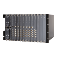
VM-701 VIBRATION / DISPLACEMENT
MONITOR MODULE
Page 1 of 4
VM-7 SERIES
SPECIFICATIONS
30901E1.3
Issued Feb. 2009
Revised Jun. 2010
Non-incendive *
1
Custom set up Tropical spec. I/O terminal block for:
1
Class I Division 2 CSA
1 VM-761 instrument rack
2 VM-762 instrument rack
*1 In future
INPUT
Input points : Max. 4ch.
Input impedance : Approx. 50kΩ
(Current signal input: Approx. 250Ω)
INPUT TRANSDUCER
Displacement vibration input : FK-202F, FK-452F, VK-202A, VK-452A,
VK-202P, VK-302P, VC-020
Velocity vibration input : CV-88, CV-87, CV-86
Acceleration vibration input : CA-302, CA-72
Displacement input : FK-202F, FK-452F, VK-202A, VK-452A,
VK-302P, VK-602P, VK-143P, VK-263P,
Other input : VC-253,
VM-11P, VM-21P
Voltage/Current signal
(-10V to +10V , 1 to 5V , 4 to 20mA)
OUTPUT
Indicators : OK LED (Green)
Monitor output : Input signal is output via buffer amplifier.
Output impedance : Approx. 100Ω (Max.0.5mA)
Recorder output : Voltage or current output proportional monitor range.
Output range : 1 to 5VDC, 4 to 20mADC
0 to 5VDC, 0 to 10VDC
I/O conversion accuracy : ±1% of F.S. at 25°C
*
2
±2% of F.S. at 0°C to 65°C *
2
Max. load resistance: 600Ω (current mode)
Output impedance: Approx. 500Ω (voltage mode)
Insulation resistance: 10MΩ at 100VAC
Burnout function: Downscale 0%
Downscale 0mA / 0mV
Transducer power supply :
Proximity transducer : -24VDC/25mA Max.
Piezoelectric transducer : +24VDC/4mA (constant current)
Alarm contact :
Number of relay : 6 points (logic changeable)
Contact type : Dry contact (SPDT)
Contact capacity : 250VAC / 5A, 30VDC / 5A
Note) *2 At calibrate frequency.
ALARM
Alarm set point : Vibration monitoring
2 points (DANGER, ALERT), from 0 to 100% of
monitor range, field changeable
Displacement monitoring
4 points (H-DANGER, H-ALERT, L-DANGER,
L-ALERT), from 0 to 100% of monitor range,
field changeable
Alarm set accuracy : ± (0.2% of F.S. +1digit) or less at 25°C
Alarm set repeatability : ±1digit or less at 25°C
Alarm delay time : 0.5, 1 to 99sec, (1 sec step, field changeable)
Alarm reset : AUTO-RESET or SELF-HOLD field changeable.
Alarm contact mode : Normally de-energized / Normally energized
Alarm bypass function : Block off alarm output (DANGER)
VIBRATION MONITORING
Accuracy : ±1% of F.S. at 25°C*
3
±2% of F.S. at 0°C to 65°C
*
3
Recommend monitoring range
: 100 to 1000μm, 10 to 100mm/s, 1 to 20G
HPF : 2Hz to 1kHz (-3dB), field changeable.
*
4
(4
th
-order / 10
th
-order)
LPF : 200Hz to 10kHz (-3dB), field changeable. *
4
(4
th
-order)
Note) *3 At calibrate frequency.
*4 There is un-match combination.
Sequence function : Used to prevent alarm output that is caused by excessive
vibration during machine startup. Block off the
DANGER/ALERT alarm, or switch the alarm setup value to
another number magnified by setup number.
Sequence Setup : Block off
1 to 10 (1 step, field changeable)
Suppression function : If the vibration value is less than the setup value,
this function is forced to suppress the measured vibration
value and recorder output.
*5 Suppression Setup Value: 0 to 5%
( 0.1% step, field changeable)
DISPLACEMENT MONITORING
Accuracy : ±1% of F.S. at 25°C
±2% of F.S. at 0°C to 65°C
Frequency response : Approx. 0.5Hz (-3dB)
Zero shift function : -50 to +50% of monitor range
Lamp angle (θ) : 4 to 90 degree
Type 1
Type 1
Type 2
Type 3
Operation function : Addition / Subtraction
1ch + 2ch, 3ch + 4ch
1ch - 2ch, 3ch - 4ch
Specification
θ
Sensor
Sebsor
θ
Sebsor
Sensor
θ
Sensor Sensor 2
θ
Sensor
Sensor
Model Code / Additional Spec. Code ( )
No entry if additional
spec, code is not specified.
! WARNING
In case the SEQ. magnification number is setup from 2 to 10, the
alarm setup value magnified by setup number while the SEQ.
circuit is in progress should stay at or lower than 110% of the
maximum monitor range. If the number is more than 110% of the
monitor range the alarm may not output.
0 100(%)
Input
100(%)
OUTPUT
DISPLAY
0
Input / Output characteristic
5
*
5
VM-701 /NB1 /CSU /TRP /TB
 Loading...