VM-7 System Manual
Chapter 2 Description of the System
23
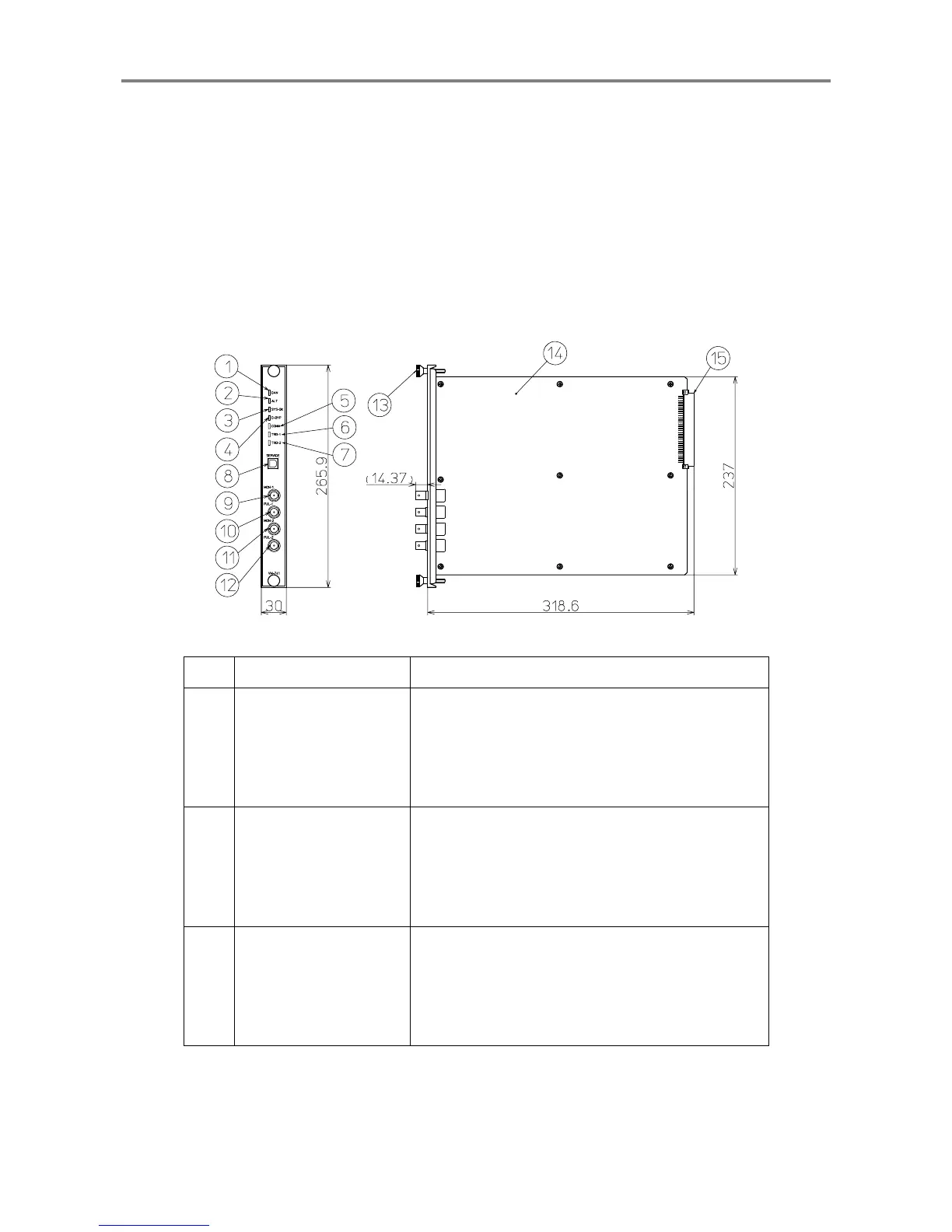
<Local Communication & Phase Marker Module (VM-741)>
The Local Communication & Phase Marker Module serves as an interface for each monitor
module, display PC and service PC. It also detects and indicates the DANGER, ALERT, OK
alarm of each module installed in the instrument rack.
It is also input the phase marker signals, and feeds each module with standard signals via the
motherboard.
The Local Communication & Phase Marker Module can be installed on Slot 0 of the instrument
rack only.
No. Name Function
①
DANGER alarm
indicator
Normal: Does not light.
When the DANGER alarm is activated: Lights (in
red).
(
When DANGER alarm is output from any of the
modules in the instrument rack
)
②
ALERT alarm indicator
Normal: Does not light.
When the ALERT alarm is activated: Lights (in
yellow).
(
When ALERT alarm is output from any of the
modules in the instrument rack
)
③
SYSTEM-OK indicator
Normal: Lights (in green).
When the OK alarm is activated: Flashes.
(
When the phase marker signal input is not normal or
when OK alarm including POWER-OK is output from
any of the modules
)
 Loading...