VM-7 System Manual
Chapter 2 Description of the System
9
<Instrument Rack (VM-76)>
An instrument rack comes in two different models: a Eurotype input/output terminal type
(VM-761) and a batch input/output panel connector type (VM-762).
An instrument rack is an assembly to accommodate each module and fix it onto the panel.
All the modules are mounted in the slots inside an instrument rack.
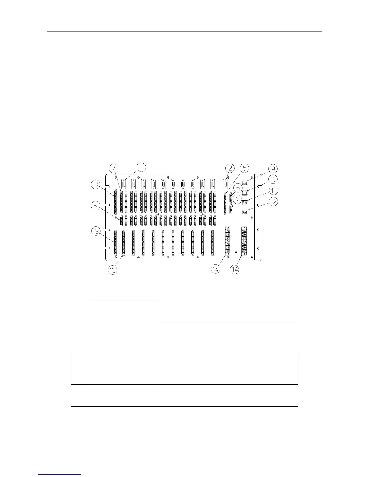
I/O terminals or connectors are located on the back of the instrument rack, and cables are
connected to them.
The size of the rack conforms to EIA standards.
European I/O terminal type Instrument Rack (VM-761)
No. Name Function
①
Monitor output
connector
Provides monitor outputs (buffer output or shaped
rotary pulse output).
②
Monitor output
connector for phase
marker
Provides buffer output and pulse output of the phase
marker.
③
18-Channel Relay
Module output terminal
block
Provides contact signals according to the logic set by
18-Channel Relay Module.
④
Transducer input
terminal block
Inputs transducer signals which correspond to each
module.
⑤
Phase marker input
terminal block
Inputs phase marker signals.
 Loading...