VM-7 System Manual
Chapter 2 Description of the System
25
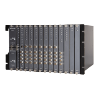
<Network Communication Module (VM-742)>
The Network Communication Module transmits the static data of each module using
Modbus/TCP.
Up to 2 modules can be installed in the instrument rack so that the upper network communication
becomes redundant.
The Network Communication Module can be installed in Slot 1 or 2 only in the instrument rack.
No. Name Function
①
Module status indicator
When the module is normal: Lights (in green).
When the module has a problem: Does not light.
When the module is installed in other than Slot 1 or
2: Flashes.
②
Communication
situation indicator
Communication connected: Lights (in green).
Communication disconnected: Does not light.
During data reception/transfer: Flashes.
③
Module fastener
This is used to fix the
Network Communication
Module
to the instrument rack.
④
Main board A board on which electronic parts are mounted
⑤
DIN connector A connector used for connecting to the motherboard
 Loading...