VM-7 System Manual
Chapter 2 Description of the System
26
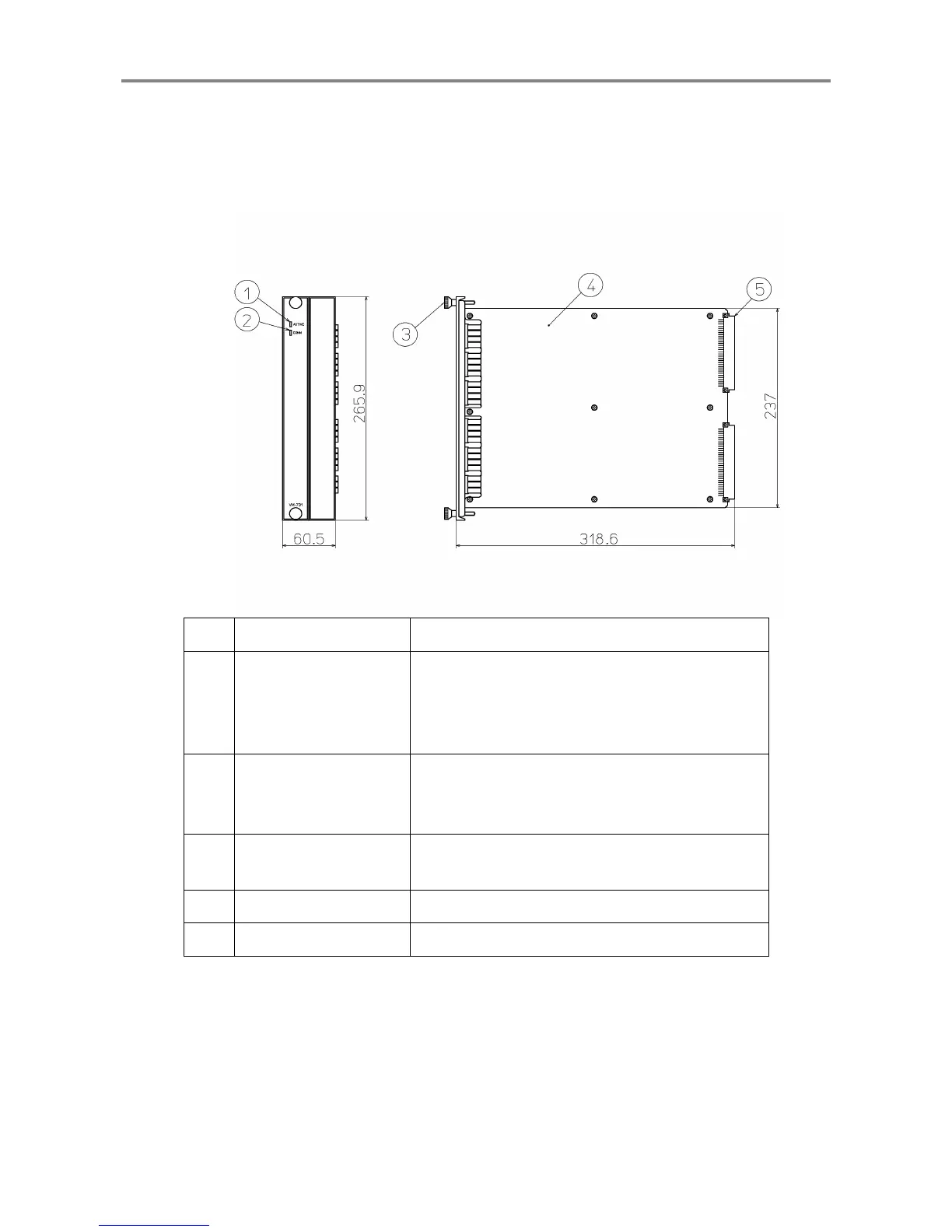
<Analysis Module (VM-731)>
The Analysis Module transmits the analysis data of each module using Ethernet (100Base-T), e.g.
waveform, overall, vector of vibration.
The Analysis Module can be installed in Slot 8 and 9 or Slot 9 and 10 only in the instrument rack.
No. Name Function
①
Module status indicator
When the module is normal: Lights (in green).
When the module has a problem: Does not light.
When the module is installed in other than
Slot 8 and
9 or Slot 9 and 10
: Flashes.
②
Communication
situation indicator
Communication connected: Lights (in green).
Communication disconnected: Does not light.
During data reception/transfer: Flashes.
③
Module fastener
This is used to fix the
Network Communication
Module
to the instrument rack.
④
Main board A board on which electronic parts are mounted
⑤
DIN connector A connector used for connecting to the motherboard
 Loading...