VM-7 System Manual
Chapter 2 Description of the System
27
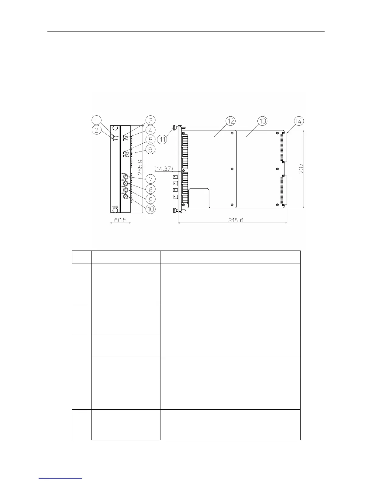
<Analysis Module (VM-732)>
The Analysis Module transmits the analysis data of each module using Ethernet (100Base-T), e.g.
waveform, overall, vector of vibration.
This module provides up to two channels for phase marker signals.
The Analysis Module can be installed in Slot 8 and 9 or Slot 9 and 10 only in the instrument rack.
No. Name Function
①
Module status indicator
When the module is normal: Lights (in green).
When the module has a problem: Does not light.
When the module is installed in other than
Slot 8 and
9 or Slot 9 and 10
: Flashes.
②
Communication
situation indicator
Communication connected: Lights (in green).
Communication disconnected: Does not light.
During data reception/transfer: Flashes.
③
3ch OK indicator
When 3ch is normal: Lights (in green).
When 3ch OK alarm is activated: Flashes.
④
4ch OK indicator
When 4ch is normal: Lights (in green).
When 4ch OK alarm is activated: Flashes.
⑤
3ch trigger indicator
Normal: Light (in yellow).
When the 3ch rotary pulse is detected: Does not
light.
⑥
4ch trigger indicator
Normal: Light (in yellow).
When the 4ch rotary pulse is detected: Does not
light.
 Loading...