VM-7 System Manual
Chapter 2 Description of the System
10
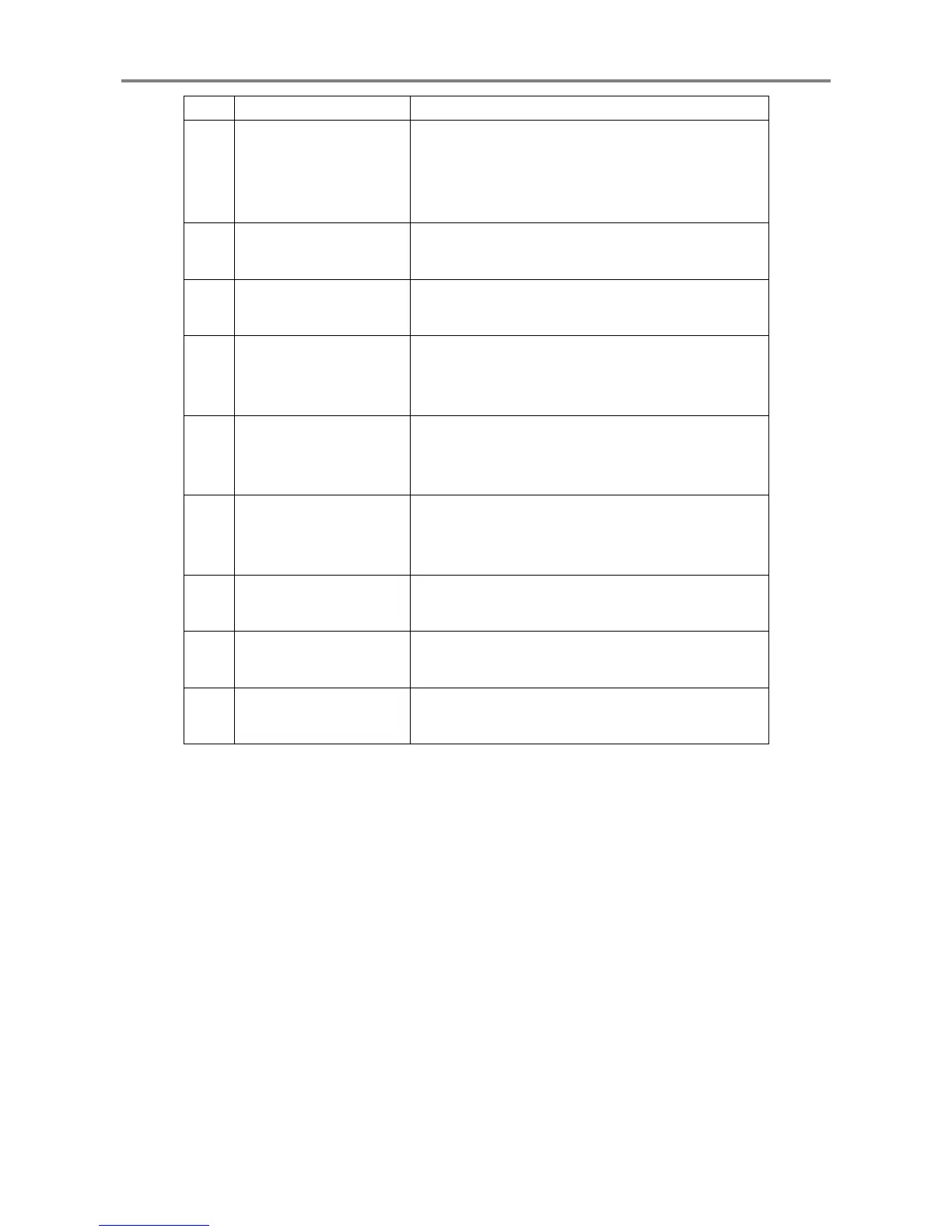
No. Name Function
⑥
Contact input terminal
block
Performs the following according to contact inputs.
y Self-hold alarm reset
y Activation of sequence function
y Activation of 10 pole high pass filter
⑦
System-OK output
terminal block
Provides contact outputs according to OR of OK
alarm from each module.
⑧
Recorder output
terminal block
Outputs the voltage or current signal proportional to
each module monitor range.
⑨
Analysis Module
communication
connector
Outputs data processed by the Analysis Module.
⑩
Network communication
connector 1
The measurement value and status of each monitor is
transmitted to the network via the Network
Communication Module installed on the Slot 1.
⑪
Network communication
connector 2
The measurement value and status of each monitor is
transmitted to the network via the Network
Communication Module installed on the Slot 2.
⑫
Local communication
connector
Communicates with the PC in which MCL View and
FIELD CONFIG are installed.
⑬
Contact output terminal
block
Outputs contact signals according to the logic related
to each module warning.
⑭
Power supply module
terminal block
Supplies power and provides POWER-OK contact
output.
 Loading...